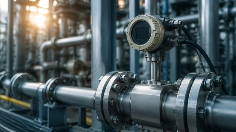
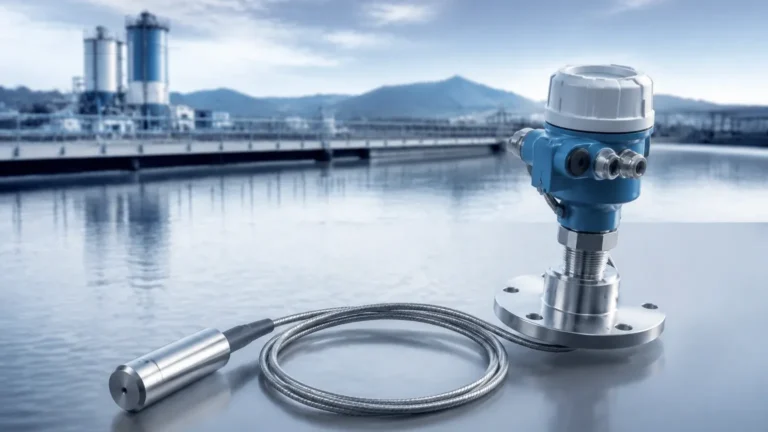
Sanitary Pressure Transducer
Sanitary Pressure Transducer
In the realms of food processing, beverage production, pharmaceuticals, and biotechnology, maintaining a sterile environment is not merely a preference but a regulatory requirement. The sanitary pressure transducer serves as a critical component in these industries, providing precise pressure and level data while ensuring that the process media remains uncontaminated. This article explores the technical foundations, design requirements, and selection criteria for these specialized instruments, focusing on their role in modern industrial automation.
Understanding the Measurement Principles
A sanitary pressure transducer operates by converting physical pressure into an electrical signal. The core of the device is a sensing element, which typically utilizes one of several physical principles to detect changes in force.
Piezoresistive Sensing
Piezoresistive sensors are among the most common in industrial applications. They consist of a diaphragm with integrated strain gauges. When pressure is applied to the diaphragm, it deforms slightly, changing the electrical resistance of the strain gauges. This change is proportional to the pressure and is converted by internal electronics into a standard output signal, such as 4-20 mA or 0-10 V. In a sanitary pressure transducer, the diaphragm is usually made of high-grade stainless steel (316L) or Hastelloy to ensure compatibility with cleaning agents.
Capacitive Sensing
Capacitive transducers measure the change in electrical capacitance between a flexible diaphragm and a fixed backplate. As pressure moves the diaphragm, the distance between the plates changes, altering the capacitance. These sensors are known for their high sensitivity and robustness, particularly in low-pressure ranges. They are often preferred in applications where high overpressure protection is required.
Hydrostatic Level Measurement
In many liquid storage applications, a sanitary pressure transducer is used to determine the level of the contents within a tank. This is based on the principle of hydrostatic pressure, where the pressure at the bottom of a vessel is directly proportional to the height of the liquid column and its density ($P = \rho \cdot g \cdot h$). By installing a transducer at the base of a tank, operators can accurately monitor volume and inventory without the need for top-mounted mechanical probes.
Design Standards for Hygienic Applications
Standard industrial pressure sensors often feature internal cavities, threads, or rough surfaces where bacteria can accumulate. A sanitary pressure transducer is engineered specifically to eliminate these "dead legs" and facilitate effective cleaning.
3-A and EHEDG Compliance
To be classified as "sanitary," instruments must often meet standards set by organizations like 3-A Sanitary Standards, Inc. or the European Hygienic Engineering & Design Group (EHEDG). These standards dictate the materials used, the smoothness of the surfaces, and the geometry of the process connection to ensure that the device can be fully sterilized.
Surface Finish and Materials
The wetted parts of the transducer—those in contact with the product—must be non-reactive and non-absorbent. 316L stainless steel is the industry standard due to its corrosion resistance. Furthermore, the surface finish is strictly controlled, typically requiring a Roughness Average (Ra) of less than 0.8 μ m (32 μ in). Electropolishing is often employed to achieve an even smoother finish, reducing the ability of microorganisms to adhere to the metal.
Flush Diaphragm Design
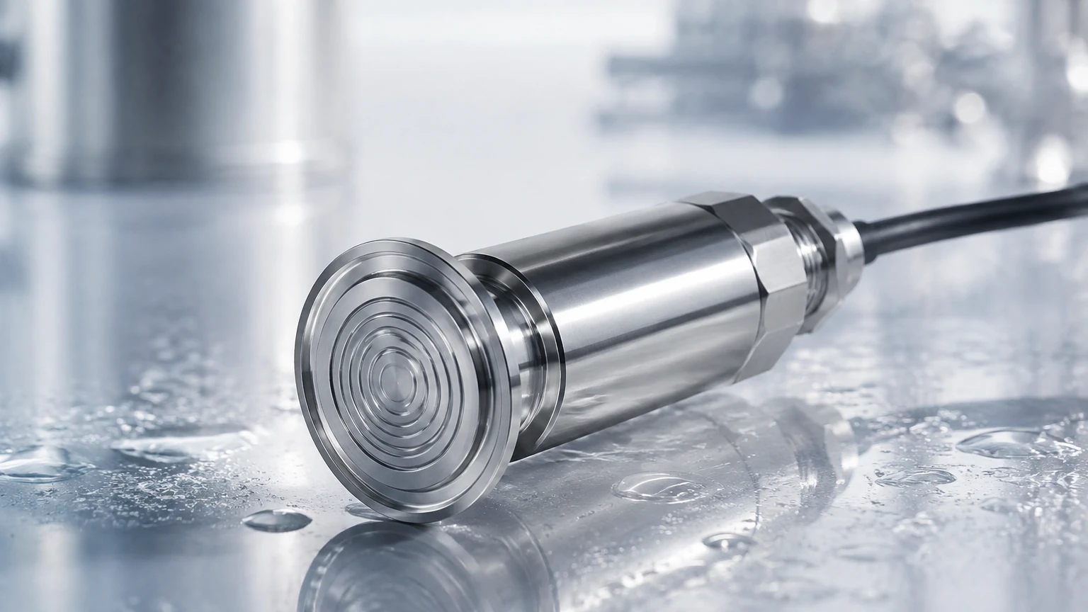
Unlike standard sensors that may have a small orifice leading to the sensing element, a sanitary pressure transducer features a flush diaphragm. This design ensures that the process media flows directly across the face of the sensor, preventing material buildup and allowing Clean-in-Place (CIP) systems to reach all surfaces effectively.
Selection Criteria and Technical Specifications
Choosing the correct sanitary pressure transducer requires a detailed understanding of the process environment. Engineers must evaluate several factors to ensure long-term reliability and accuracy.
Pressure Range and Overpressure
The selected range should cover the maximum expected operating pressure while providing enough resolution for low-pressure monitoring. It is also vital to consider the overpressure rating; in systems where water hammer or pump surges occur, the sensor must be able to withstand momentary spikes without losing calibration or sustaining damage.
Temperature Limits and Thermal Shock
Sanitary processes often involve extreme temperature fluctuations. For example, a sensor might monitor a product at 4°C (40°F) and then immediately undergo a Steam-in-Place (SIP) cycle at 130°C (266°F). The transducer must be temperature-compensated to prevent "thermal drift," where the output signal fluctuates due to temperature changes rather than actual pressure changes.
Selection Table: Comparison of Sanitary Transducer Features
| Feature | Standard Sanitary | High-Temperature / SIP | Low-Pressure / Level |
| :— | :— | :— | :— |
| Sensing Tech | Piezoresistive | Piezoresistive with cooling | Capacitive |
| Accuracy | ±0.5% FS | ±0.25% to ±0.5% FS | ±0.1% to ±0.2% FS |
| Process Temp | -20 to 80°C | -20 to 150°C (short term) | -10 to 60°C |
| Connection | 1.5" Tri-clamp | 2.0" Tri-clamp / Varivent | 3.0" Flush Flange |
| Output | 4-20mA | 4-20mA / HART | 4-20mA / IO-Link |
For more information on selecting the right instrumentation for your specific industrial application, you can review product options and application support on our Main Page.
Installation Guidelines and Best Practices
Correct installation is as important as the selection of the instrument itself. Improper mounting can lead to inaccurate readings or hygiene failures.
1. Orientation for Drainage: Transducers should be mounted in a position that allows for complete drainage of the process fluid and cleaning solutions. In horizontal pipelines, mounting the sensor on the side or bottom (depending on the media) prevents air pockets or sediment buildup.
2. Gasket Selection: Only use sanitary-grade gaskets (e.g., EPDM, PTFE, or FKM) that match the process chemistry and temperature requirements. A mismatched gasket can degrade, leading to leaks or contamination.
3. Torque and Clamping: When using Tri-clamp connections, ensure the clamp is tightened sufficiently to create a seal but not so tight that it deforms the gasket into the flow path, creating a hygienic risk.
4. Venting: For gauge pressure sensors, ensure the atmospheric vent (usually located in the cable or a dedicated vent plug) is kept clear and protected from moisture ingress. If the vent is blocked, the sensor will not accurately compensate for changes in barometric pressure.
Limitations and Common Risks
While highly effective, sanitary pressure transducers have specific limitations that must be managed.
* Diaphragm Fragility: The flush diaphragms are extremely thin (often less than 0.1 mm) to maintain sensitivity. They can be easily damaged by mechanical impact during cleaning or by abrasive particles in the process fluid.
* Vacuum Sensitivity: Some piezoresistive sensors can be damaged by deep vacuum conditions if they are not specifically designed for it. This is a common risk during the cooling phase after an SIP cycle, where steam condenses and creates a vacuum.
* Signal Noise: Long cable runs in environments with heavy electrical machinery (like large pumps or mixers) can introduce EMI (Electromagnetic Interference). Using shielded cables and 4-20 mA current loops helps mitigate this risk.
Frequently Asked Questions (FAQ)
Q: How often should a sanitary pressure transducer be calibrated?
A: Calibration frequency depends on the criticality of the process and the stability of the sensor. In regulated industries like pharmaceuticals, annual or semi-annual calibration is standard. In food and beverage, calibration may be performed during scheduled maintenance shutdowns.
Q: Can I use a standard pressure gauge in a sanitary application?
A: No. Standard gauges often have internal voids and threaded connections that cannot be cleaned, making them a source of bacterial contamination. Always use a dedicated sanitary pressure transducer or a gauge with a sanitary diaphragm seal.
Q: What is the difference between a pressure transmitter and a transducer?
A: In common industrial usage, a "transducer" refers to the component that converts the physical force to a low-level electrical signal (like millivolts), while a "transmitter" includes additional electronics to convert that signal into a standardized industrial output (like 4-20 mA). However, the terms are often used interchangeably in B2B contexts.
Q: How do I handle sensors during CIP cycles?
A: Ensure the sensor is rated for the chemicals and temperatures used in your CIP process. Most sanitary sensors are designed to remain in place during cleaning, provided the temperature limits of the electronics are not exceeded.
Conclusion
The sanitary pressure transducer is an indispensable tool for ensuring product quality and safety in hygienic industries. By understanding the underlying measurement principles and adhering to strict design and installation standards, facilities can achieve accurate pressure and level monitoring while complying with global health regulations. When selecting these components, engineers must balance precision requirements with the harsh realities of the processing environment, including thermal shock and chemical exposure. For a comprehensive range of level and pressure measurement solutions tailored to industrial automation, visit the Main Page to explore technical specifications and expert support.