Sensor Temperature Rtd
Sensor Temperature Rtd
In the landscape of industrial process control, the accuracy of temperature data is often the foundation upon which other measurements—such as pressure, flow, and level—are built. The Resistance Temperature Detector, commonly referred to as an RTD, is a primary instrument used to achieve high-precision temperature monitoring. A sensor temperature rtd operates on a predictable physical principle: the electrical resistance of a metal changes in direct proportion to changes in temperature.
For engineers and procurement professionals seeking reliable measurement solutions, understanding the nuances of RTD technology is essential for ensuring process stability and safety. For a comprehensive overview of industrial measurement instruments that incorporate these technologies, you may visit the Main Page of our technical catalog.
Measurement Principles of RTDs
The fundamental principle behind a sensor temperature rtd is the Positive Temperature Coefficient (PTC) of metals. As the temperature of a metal increases, the thermal agitation of its atoms increases, which in turn hinders the flow of electrons, resulting in higher electrical resistance.
The Material Standard: Platinum
While various metals like nickel, copper, and tungsten can be used, platinum has become the industry standard for high-quality RTDs. Platinum offers a highly linear resistance-to-temperature relationship, excellent stability, and resistance to oxidation and corrosion over a wide range of temperatures.
The most common RTD is the Pt100, which has a resistance of 100 ohms at 0°C. Another frequently used variant is the Pt1000, offering 1000 ohms at 0°C. The relationship is governed by the Callendar-Van Dusen equation, though for most industrial applications within a standard range, the relationship is approximately linear with a temperature coefficient (Alpha) of 0.00385 Ω/Ω/°C.
Resistance vs. Temperature (Pt100 Example)
| Temperature (°C) | Resistance (Ohms) |
| :— | :— |
| -50 | 80.31 |
| 0 | 100.00 |
| 50 | 119.40 |
| 100 | 138.51 |
| 150 | 157.33 |
| 200 | 175.86 |
Types of Sensor Temperature RTD Constructions
There are two primary ways to construct the sensing element of an RTD: wire-wound and thin-film. Each has specific advantages depending on the industrial environment.
Wire-Wound Elements
Wire-wound RTDs consist of a very fine, high-purity platinum wire wrapped around a ceramic or glass core. This assembly is then sealed within a protective coating.
- Advantages: Highest accuracy and stability over long periods; suitable for extreme temperature ranges.
- Limitations: More expensive to manufacture and more susceptible to damage from high-vibration environments.
Thin-Film Elements
Thin-film RTDs are manufactured by depositing a thin layer of platinum onto a ceramic substrate using vacuum deposition or sputtering. The layer is سپس etched to create the required resistance path.
- Advantages: Highly resistant to vibration, smaller footprint, faster response time, and lower cost.
- Limitations: Generally limited to lower temperature ranges than wire-wound versions and slightly less stable over many years of service.
Wiring Configurations and Lead Wire Compensation
One of the most critical factors in the accuracy of a sensor temperature rtd is how it is wired to the control system. Because the RTD measures resistance, the resistance of the copper lead wires connecting the sensor to the transmitter can introduce errors.
2-Wire Configuration
This is the simplest but least accurate method. The resistance of the lead wires is added directly to the sensor resistance, causing a positive temperature offset. It is only recommended for applications where the lead wires are very short or high accuracy is not required.
3-Wire Configuration
This is the industrial standard. By adding a third wire, the control system can measure the resistance of the lead loops and subtract it from the total resistance. This assumes all three wires have identical resistance and are subjected to the same ambient temperatures.
4-Wire Configuration
Used primarily in laboratory settings or for extremely high-precision industrial processes, the 4-wire configuration completely eliminates the effect of lead wire resistance. Two wires carry the excitation current, while the other two measure the voltage drop across the RTD element using a high-impedance circuit.
Integration with Level Measurement Systems
In the context of industrial automation, a sensor temperature rtd is rarely a standalone device. It plays a vital role in correcting and calibrating level measurement data.
Hydrostatic Level Measurement
Hydrostatic level transmitters measure the pressure exerted by a liquid column. However, the density of a liquid changes with its temperature. To maintain accuracy in tanks where temperature fluctuates, an RTD provides real-time temperature data to the PLC or transmitter, allowing for dynamic density compensation.
Ultrasonic and Radar Level Sensors
In ultrasonic level measurement, the speed of sound through the air or gas above the liquid is highly dependent on temperature. An integrated sensor temperature rtd within the ultrasonic transducer housing allows the sensor to adjust its distance calculations based on the current air temperature. While radar level meters (GWR or non-contact) are less affected by temperature changes in the gas phase, RTDs are still used to monitor the process temperature for safety and product quality control.
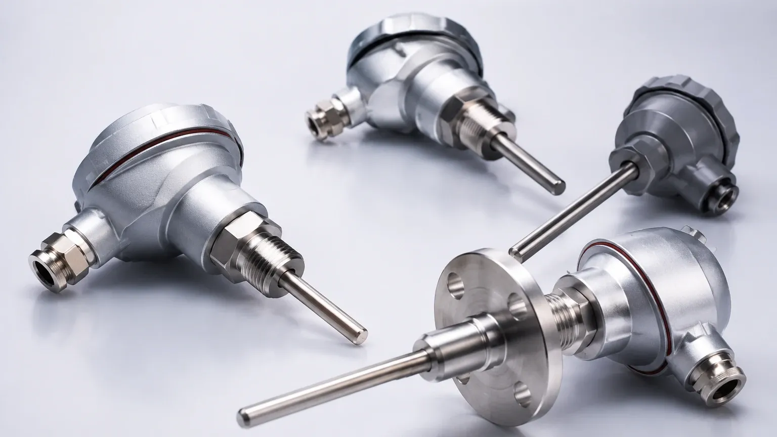
Practical Selection Table for Industrial Applications
When selecting a temperature sensor, engineers must balance accuracy, range, and environmental conditions.
| Criteria | Thin-Film Pt100 | Wire-Wound Pt100 | Thermocouple (Type K) |
| :— | :— | :— | :— |
| Temperature Range | -50°C to +500°C | -200°C to +850°C | -200°C to +1260°C |
| Accuracy | High (Class A/B) | Very High (Class AA) | Moderate |
| Vibration Resistance | Excellent | Fair | Excellent |
| Response Time | Fast | Moderate | Very Fast |
| Cost | Low to Moderate | High | Low |
| Stability | Good | Excellent | Fair |
Installation and Engineering Considerations
Proper installation is paramount to ensure the sensor temperature rtd provides a true representation of the process temperature rather than the ambient environment.
1. Thermowell Selection: In pressurized or corrosive pipes and tanks, the RTD should be installed inside a thermowell. This allows for the removal of the sensor without breaking the process seal. The material of the thermowell (e.g., 316 Stainless Steel, Hastelloy) must be compatible with the process media.
2. Immersion Depth: To avoid "stem conduction" errors (where heat travels along the sensor sheath to the outside air), the sensor should be immersed to a depth at least 10 times the diameter of the protective sheath.
3. Lagging and Insulation: In outdoor or high-temperature applications, insulating the connection head and the exposed part of the thermowell prevents ambient air from cooling or heating the sensor junction.
4. Vibration Dampening: If the application involves high-flow rates or mechanical vibration, thin-film RTDs or specialized ruggedized housings should be specified to prevent mechanical failure of the platinum element.
Limitations of RTD Technology
While RTDs are exceptionally accurate, they have specific limitations that must be managed:
- Self-Heating: To measure resistance, a small current must be passed through the RTD. This current generates a tiny amount of heat. If the excitation current is too high (typically >1mA), it can cause a false high-temperature reading.
- Fragility: Compared to thermocouples, the ceramic components and fine wires in an RTD are more susceptible to mechanical shock.
- Cost: RTDs are generally more expensive than thermocouples, especially when high-purity platinum or specialized 4-wire configurations are required.
Frequently Asked Questions (FAQ)
Q: How do I know if I should use a Pt100 or a Pt1000?
A: Pt100 is the standard for most industrial transmitters and PLCs. Pt1000 is often used in battery-powered applications or where lead wire resistance is a concern in 2-wire setups, as the higher base resistance makes the lead wire error proportionally smaller.
Q: What is the difference between Class A and Class B RTDs?
A: These are tolerance classes defined by international standards (IEC 60751). Class A sensors have a tighter tolerance (±0.15°C at 0°C) compared to Class B (±0.30°C at 0°C). Class AA (formerly 1/3 DIN) is even more precise.
Q: Can I use an RTD for temperatures above 850°C?
A: Generally, no. At these extreme temperatures, platinum can become contaminated, and the insulation resistance of the ceramic internal components breaks down. For temperatures above 850°C, thermocouples (such as Type R, S, or B) are the preferred choice.
Q: How often should a sensor temperature rtd be calibrated?
A: In critical B2B process environments, annual calibration is standard. However, RTDs are known for their excellent stability, often drifting less than 0.1°C per year in stable conditions.
For technical support regarding the integration of temperature sensors into your level measurement projects, or to view specific product datasheets, please refer to the Main Page for our full range of industrial instrumentation solutions.