Sequestri Carbon Storage Solutions
Sequestri Carbon Storage Solutions
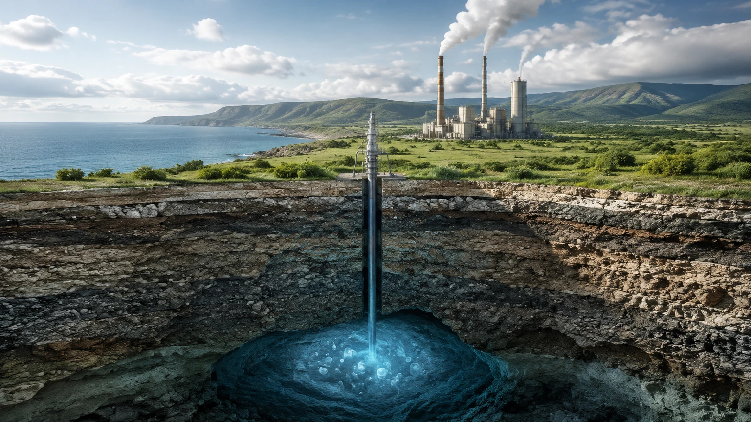
Carbon Capture and Storage (CCS) has transitioned from a theoretical climate mitigation strategy to a critical industrial requirement. As global industries strive to meet net-zero targets, the implementation of sequestri carbon storage solutions—the systems and technologies used to safely contain captured CO2—has become a priority for power generation, cement manufacturing, and steel production.
Effective carbon sequestration relies on the ability to monitor and manage CO2 across various physical states, including gaseous, liquid, and supercritical phases. For engineers and site managers, selecting the correct level measurement instrumentation is vital to ensure the structural integrity of storage vessels, optimize storage capacity, and maintain rigorous safety standards. This guide explores the technical principles of level measurement within the context of carbon storage and provides a framework for selecting the appropriate technology.
Understanding the Infrastructure of Carbon Sequestration
Sequestri carbon storage solutions typically involve the long-term containment of carbon dioxide in deep geological formations or specialized surface pressurized vessels. Before CO2 is injected into saline aquifers or depleted oil and gas reservoirs, it is often held in intermediate storage tanks at high pressures and low temperatures to maintain its liquid or supercritical state.
In these environments, level measurement serves three primary functions:
1. Inventory Management: Tracking the volume of captured CO2 to ensure efficient logistics and reporting.
2. Overfill Prevention: Protecting high-pressure vessels from over-pressurization or mechanical failure caused by exceeding volume limits.
3. Process Control: Managing the transition of CO2 between different stages of the sequestration chain, such as from capture to compression and finally to injection.
Because CO2 behaves differently than standard industrial fluids, particularly near its critical point (31.1°C and 73.8 bar), the instrumentation used must be capable of handling rapid changes in density and dielectric properties.
Measurement Principles for CO2 Level Monitoring
Before selecting a specific instrument for sequestri carbon storage solutions, it is essential to understand the underlying physical principles that govern level detection in these applications.
Time-of-Flight (ToF)
Technologies such as radar and ultrasonic sensors rely on the Time-of-Flight principle. The sensor emits a signal (electromagnetic for radar, sound waves for ultrasonic) that travels to the surface of the CO2 and reflects back to the receiver. The distance is calculated based on the time elapsed and the speed of the signal. In carbon storage, radar is often preferred because electromagnetic waves are less affected by the dense gas layers often found above liquid CO2 compared to sound waves.
Buoyancy and Magnetic Coupling
Magnetic level gauges utilize a float containing a permanent magnet. As the liquid level changes, the float moves accordingly, and its position is transmitted to an external indicator or transmitter via magnetic coupling. This principle is highly effective for high-pressure storage because it provides a physical, visual indication without requiring a direct opening into the pressurized vessel environment.
Hydrostatic Pressure
Hydrostatic measurement calculates the level by measuring the pressure exerted by the column of liquid CO2. The formula used is $P = \rho \cdot g \cdot h$, where $P$ is pressure, $\rho$ is the density of the fluid, $g$ is gravity, and $h$ is the height of the liquid. While reliable, this method requires accurate knowledge of the fluid's density, which can fluctuate significantly in carbon sequestration processes due to temperature and pressure changes.
Comparative Analysis of Level Measurement Technologies
Choosing the right technology requires balancing accuracy, pressure ratings, and maintenance requirements. The following table provides a comparison of common instruments used in sequestri carbon storage solutions.
| Technology | Measurement Principle | Typical Pressure Range | Temperature Range | Suitability for CO2 Storage |
| :— | :— | :— | :— | :— |
| Guided Wave Radar (GWR) | Time-of-Flight (Contact) | Up to 400 bar | -200°C to 450°C | Excellent for liquid and supercritical CO2; unaffected by density changes. |
| Non-Contact Radar (80GHz) | Time-of-Flight (Non-contact) | Up to 160 bar | -40°C to 200°C | Ideal for large storage tanks; provides high precision without fluid contact. |
| Magnetic Level Gauge | Buoyancy/Magnetic | Up to 320 bar | -196°C to 450°C | Best for high-pressure visual monitoring and redundant electronic output. |
| Ultrasonic Sensor | Time-of-Flight (Sound) | Atmospheric to 3 bar | -40°C to 80°C | Limited to low-pressure buffer tanks or water treatment stages of CCS. |
| Hydrostatic Transmitter | Pressure Differential | Up to 600 bar | -40°C to 120°C | Good for deep well monitoring, but requires density compensation. |
For a comprehensive overview of available hardware and technical support for these applications, professionals should review the product options on the Main Page of the Welk industrial catalog.
Selection Criteria for Sequestri Carbon Storage Solutions
When evaluating instrumentation for a carbon storage project, several technical factors must be confirmed to ensure long-term reliability.
1. Operating Phase of CO2
Is the CO2 being stored as a refrigerated liquid, a pressurized gas, or in a supercritical state? Supercritical CO2 has a dielectric constant that varies with pressure, which can affect the signal strength of radar sensors. In such cases, Guided Wave Radar (GWR) with a coaxial probe is often the most robust choice as it concentrates the signal and provides a stable reference.
2. Vessel Geometry and Internal Obstructions
Large-scale sequestration tanks often feature internal reinforcements, heating coils, or agitators. Non-contact radar sensors with narrow beam angles (such as 80GHz units) are better at avoiding these obstructions than wider-beam 26GHz units or ultrasonic sensors.
3. Material Compatibility
CO2 in the presence of moisture can form carbonic acid, which is corrosive to standard carbon steel. Instrumentation wetted parts should typically be constructed from 316L stainless steel, Hastelloy, or other corrosion-resistant alloys. Furthermore, seals and O-rings must be resistant to Explosive Decompression (ED), a phenomenon where CO2 gas permeates the seal and expands rapidly when pressure is dropped, causing the seal to rupture.
4. Redundancy and Safety Integrity Levels (SIL)
Given the environmental and safety risks associated with CO2 leaks, many sequestri carbon storage solutions require instruments with SIL 2 or SIL 3 certification. Utilizing a combination of technologies—such as a magnetic level gauge for local indication and a radar transmitter for remote monitoring—provides the necessary redundancy for safety-critical systems.
Installation and Safety Guidelines
Proper installation is as critical as instrument selection. For sequestri carbon storage solutions, the following practices are recommended:
* Nozzle Configuration: For radar installations, ensure the nozzle height and diameter do not interfere with the signal beam. For GWR, the probe should be installed away from the tank wall to prevent signal interference.
* Sealing and Isolation: Use high-pressure flanges (e.g., ANSI 600# or 900#) and specialized gaskets designed for high-pressure CO2 service. Isolation valves should be installed to allow for instrument maintenance without depressurizing the entire storage system.
* Stilling Wells: In tanks where turbulence is expected (e.g., during high-flow injection), installing the level sensor inside a stilling well or bypass chamber can stabilize the liquid surface and improve measurement accuracy.
* Hazardous Area Certification: Carbon storage sites are often classified as hazardous environments. Ensure all electronic components carry the appropriate ATEX, IECEx, or UL certifications for the specific zone of installation.
Technical Limitations and Environmental Factors
While modern instrumentation is highly advanced, certain limitations remain inherent to sequestri carbon storage solutions:
* Density Fluctuations: Hydrostatic and buoyancy-based measurements are sensitive to density changes. Since the density of CO2 is highly dependent on temperature, these systems must be paired with temperature sensors to provide real-time compensation.
* Gas Phase Attenuation: In very high-pressure gas phases, the density of the gas can become high enough to slow down the speed of radar waves. While this effect is minor, it may require a correction factor in high-precision custody transfer applications.
* Vapor Clouds: Rapid depressurization of CO2 can lead to the formation of dry ice or heavy vapor clouds, which can temporarily obstruct the signal of non-contact ultrasonic or optical sensors.
Frequently Asked Questions (FAQ)
Q: Can ultrasonic sensors be used for supercritical CO2 storage?
A: Generally, no. Ultrasonic sensors rely on sound waves, which are significantly affected by the extreme pressure and density changes of supercritical CO2. Radar or magnetic level gauges are far more reliable for these conditions.
Q: How does the dielectric constant of CO2 affect radar measurement?
A: Liquid CO2 has a relatively low dielectric constant (approximately 1.6). This means the reflected signal is weaker than it would be for water. High-frequency radar (80GHz) or Guided Wave Radar is recommended to ensure a strong enough return signal for accurate tracking.
Q: What maintenance is required for level sensors in carbon storage?
A: Non-contact radar requires minimal maintenance as there are no moving parts. Magnetic level gauges should be inspected periodically for debris or buildup within the chamber that could restrict float movement, especially if the captured CO2 contains impurities from the combustion process.
Q: Is it possible to measure the interface between CO2 and water in geological storage?
A: Yes, Guided Wave Radar is particularly effective at measuring the interface between two liquids with different dielectric constants, such as CO2 and saline water in a test well or separator tank.
Conclusion
Implementing reliable sequestri carbon storage solutions requires a deep understanding of both the physical properties of CO2 and the technical capabilities of modern level measurement hardware. By selecting instruments that account for high pressures, potential corrosion, and varying fluid densities, operators can ensure the safety and efficiency of their carbon sequestration infrastructure. For technical assistance in selecting the right radar, ultrasonic, or magnetic level solutions, engineers are encouraged to consult with professional manufacturers to match specific site requirements with the appropriate instrumentation technology.