Sil 2
Sil 2
In the landscape of industrial process automation, Safety Integrity Level 2 (SIL 2) represents a critical benchmark for risk management. For engineers and plant operators managing storage tanks, chemical reactors, or water treatment facilities, achieving SIL 2 compliance is not merely a regulatory hurdle but a fundamental requirement for protecting personnel, the environment, and capital assets. This guide examines the technical requirements, measurement principles, and selection criteria for level measurement instruments designed to operate within SIL 2 safety loops.
Understanding the SIL 2 Framework
Safety Integrity Level (SIL) is defined by international standards—primarily IEC 61508 (for manufacturers) and IEC 61511 (for end-users in the process industry). SIL is a measure of the reliability and performance of a Safety Instrumented Function (SIF). It is not a property of an individual instrument, but rather a property of the entire safety loop, which includes the sensor, the logic solver (PLC), and the final element (valve or pump).
SIL 2 specifically denotes a target level of risk reduction. In quantitative terms, a SIL 2 safety function must have a Probability of Failure on Demand (PFDavg) between ≥ 10⁻³ and < 10⁻². This translates to a Risk Reduction Factor (RRF) of 100 to 1,000. In practical plant operations, SIL 2 is often the standard for processes where a failure could lead to significant localized damage, minor injuries, or substantial production loss.
Core Measurement Principles in Safety Applications
Before selecting a device for a SIL 2 loop, it is essential to understand the underlying measurement physics. The reliability of the safety function depends heavily on how the technology interacts with the process media.
Radar Level Measurement (ToF)
Radar level meters utilize Time of Flight (ToF) principles. They emit electromagnetic pulses (Pulse Radar) or a continuous frequency-modulated signal (FMCW). These signals travel at the speed of light, reflect off the material surface, and return to the sensor. Because radar is non-contact and largely unaffected by density, temperature, or pressure changes, it is a preferred choice for SIL 2 overfill protection in volatile chemical tanks.
Ultrasonic Level Sensing
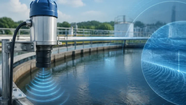
Ultrasonic sensors emit high-frequency sound waves. The time taken for the echo to return is proportional to the distance. While cost-effective for water treatment and open-channel flow, ultrasonic waves are sensitive to air temperature gradients and surface foam. In SIL 2 applications, they are typically used in stable environments like ambient water storage.
Hydrostatic Pressure
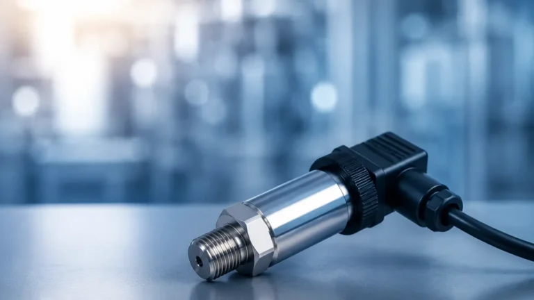
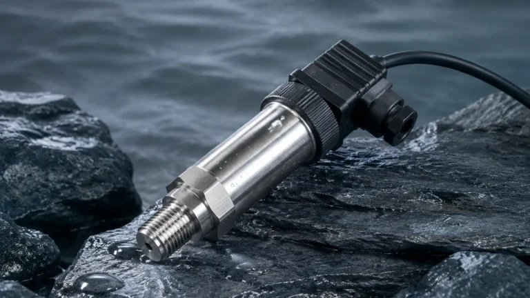
Hydrostatic transmitters measure the pressure exerted by a liquid column. Based on the formula $P = \rho gh$ (where $\rho$ is density, $g$ is gravity, and $h$ is height), the level is calculated. For SIL 2 compliance, these sensors must account for changes in liquid density and are often used in closed tanks where the vapor space pressure is compensated via differential pressure (DP) measurement.
Magnetic Level Gauges and Switches
Magnetic level gauges utilize a float containing a magnet assembly that moves within a bypass chamber. As the float rises and falls, it flips magnetic flags or actuates external reed switches. In a SIL 2 context, the magnetic switch is often used as a redundant high-high level alarm, providing a mechanical failsafe independent of electronic transmitters.
SIL 2 Evaluation Criteria for Level Instruments
When evaluating a level meter for a SIL 2 application, several technical parameters must be verified against the manufacturer’s safety manual.
1. Safe Failure Fraction (SFF): This is the percentage of total failures that are either "safe" or "detected dangerous." For a SIL 2 rating in a single-channel (1oo1) configuration, a device typically requires an SFF between 90% and 99%.
2. Diagnostic Coverage (DC): This measures the device's ability to detect its own internal faults. High-quality radar and ultrasonic units perform continuous self-checks on the microwave/transducer circuitry and the internal software.
3. Systematic Capability (SC): This indicates that the instrument has been designed and manufactured following strict quality management processes to minimize human errors during development. Welk instruments, for instance, undergo rigorous testing to ensure they meet these systematic requirements.
4. Proof Test Interval: No SIL-rated device is "set and forget." The manufacturer defines a proof test interval (e.g., 12 months or 24 months) during which the user must manually verify the device's safety function to return the PFDavg to its original state.
Technology Selection Table for SIL 2 Applications
Selecting the right technology requires balancing process conditions with safety requirements. The following table provides a comparison for common industrial scenarios.
| Technology | Typical SIL Capability | Strengths | Limitations | Common SIL 2 Application |
| :— | :— | :— | :— | :— |
| Radar (80GHz) | SIL 2 / SIL 3 | High accuracy, ignores vapor/dust | Higher initial cost | Chemical reactors, Oil storage |
| Ultrasonic | SIL 2 | Non-contact, cost-effective | Affected by foam and vacuum | Water pits, Acid tanks |
| Hydrostatic | SIL 2 | Simple installation, robust | Density dependent | Deep wells, pressurized tanks |
| Magnetic Gauge | SIL 2 (with switch) | Visual indication + alarm | Moving parts can stick | Boiler drums, bypass pipes |
| Displacer | SIL 2 | Extreme temperature/pressure | Susceptible to buildup | High-pressure separators |
Installation Considerations for SIL 2 Compliance
Even a SIL 2 certified instrument will fail to provide safety if installed incorrectly. Engineering teams must adhere to specific guidelines to maintain the integrity of the safety loop.
* Nozzle Geometry: For radar and ultrasonic sensors, the nozzle height and diameter must be optimized to prevent "ringing" or false reflections from the nozzle lip. Standard practice suggests a nozzle height-to-diameter ratio of less than 3:1 where possible.
* Stilling Wells and Bypass Chambers: In processes with heavy turbulence or surface foam, installing the sensor in a stilling well or a bypass chamber can stabilize the signal. This is particularly important for magnetic level gauges and hydrostatic sensors to prevent mechanical fatigue or pressure spikes.
* Redundancy (Hardware Fault Tolerance): While a single SIL 2 certified device can often satisfy a SIL 2 loop (1oo1 configuration), many critical applications utilize 1oo2 (one out of two) or 2oo3 (two out of three) voting logic. This increases both safety and availability, ensuring that a single instrument failure does not lead to a nuisance shutdown or a dangerous undetected state.
* Environmental Protection: Level transmitters should be equipped with sunshades in outdoor environments to prevent thermal drifting of the electronics, which could impact the diagnostic accuracy required for SIL 2.

Limitations and Common Risks
It is a common misconception that a "SIL 2 certified" device is immune to failure. The certification only quantifies the *probability* of failure. Real-world risks include:
* Media Buildup: In the chemical industry, crystallization or coating on a radar antenna or ultrasonic transducer can attenuate the signal. If the diagnostics do not recognize this as a fault, it becomes a "dangerous undetected" failure.
* Incorrect Configuration: If the safety parameters (such as the 4-20mA alarm levels) are not locked or are incorrectly scaled during commissioning, the SIL rating is effectively voided.
* Ignoring the Safety Manual: Every SIL 2 instrument comes with a specific Safety Manual. Failure to follow the prescribed mounting angles, wiring requirements, or proof-testing procedures means the loop does not meet the calculated safety level.
Maintenance and Proof Testing
To maintain a SIL 2 rating over the life of the plant, operators must perform periodic proof tests. A proof test is a documented procedure that verifies the instrument performs its intended safety function. For a high-level alarm, this might involve:
1. Physically raising the liquid level to the trip point.
2. Using a simulator to force the output to the alarm state.
3. Verifying that the logic solver and final element (e.g., an emergency shutdown valve) respond within the required safety time.
Detailed records of these tests must be kept for auditing and to ensure the PFDavg remains within the SIL 2 boundaries.
Frequently Asked Questions (FAQs)
Q: Can I use a standard level transmitter in a SIL 2 loop?
A: Only if it has been "proven in use" according to IEC 61511 standards, which requires extensive historical data. Generally, it is safer and more efficient to purchase a device that is "SIL 2 Ready" or certified by an independent body like EXIDA or TÜV.
Q: What is the difference between SIL 2 and SIL 3?
A: SIL 3 requires a much lower probability of failure (PFDavg ≥ 10⁻⁴ to < 10⁻³). In level measurement, SIL 3 is usually achieved by using two SIL 2 certified devices in a redundant configuration (1oo2).
Q: Does SIL 2 apply to the 4-20mA signal?
A: Yes. In a SIL 2 loop, the 4-20mA signal must be configured so that specific values (usually < 3.6mA or > 21mA) represent a hardware fault, allowing the PLC to trigger a safe state.
Conclusion
Implementing SIL 2 level measurement requires a holistic approach that begins with understanding the physics of the application and ends with rigorous maintenance. By selecting appropriate technologies—whether radar, ultrasonic, or hydrostatic—and adhering to the strict requirements of the safety manual, engineers can significantly reduce the risk of industrial accidents. For those seeking specific instrument specifications and engineering support for safety-critical applications, you can Review product options and application support to ensure your project meets the necessary safety integrity levels.
When designing your next safety instrumented system, remember that SIL 2 is not just a label on a datasheet; it is a commitment to operational excellence and the safety of the entire facility.