Sis Functional Testing
Sis Functional Testing
In industrial process safety, a Safety Instrumented System (SIS) serves as a critical layer of protection designed to transition a process to a safe state when predetermined conditions are violated. For industries such as chemical processing, oil and gas, and water treatment, level measurement instruments often act as the primary sensors within these safety loops. To maintain the integrity of these systems, sis functional testing—commonly referred to as proof testing—is mandatory. This process verifies that the sensors, logic solvers, and final elements will perform their intended safety function upon demand.
Regular functional testing ensures that the Probability of Failure on Demand (PFD) remains within the limits defined by the Safety Integrity Level (SIL) of the loop. Without rigorous testing, undetected dangerous failures (hidden failures) could compromise the entire safety layer, leading to catastrophic overfills, tank ruptures, or environmental releases.
Principles of Level Measurement in Safety Systems
Before implementing a functional testing regime, it is essential to understand the measurement principles of the instruments being tested. In SIS applications, the reliability of the sensing technology is paramount. Welk provides several core technologies used in safety-critical level monitoring.
Radar Level Measurement
Radar level meters operate on the Time-of-Flight (ToF) principle. The device emits high-frequency electromagnetic pulses (typically in the GHz range) toward the material surface. These pulses are reflected back to the sensor. The distance is calculated based on the time it takes for the pulse to travel to the surface and back, using the formula $D = (c \times t) / 2$, where $c$ is the speed of light and $t$ is the transit time. Radar is preferred in SIS because it is non-contact and largely unaffected by changes in pressure, temperature, or vapor space composition.
Ultrasonic Level Measurement
Similar to radar, ultrasonic sensors use ToF but employ sound waves instead of electromagnetic pulses. The sensor emits an ultrasonic pulse that reflects off the liquid surface. Because the speed of sound is influenced by air temperature, these sensors usually include integrated temperature compensation. Ultrasonic sensors are cost-effective for water treatment and open-channel applications but are limited in high-pressure or high-vacuum environments.
Hydrostatic Level Measurement
Hydrostatic transmitters measure the pressure exerted by a liquid column. The relationship is defined by $P = \rho \cdot g \cdot h$, where $P$ is pressure, $\rho$ is the density of the fluid, $g$ is gravity, and $h$ is the height of the liquid. In safety systems, hydrostatic sensors are valued for their robustness and simplicity, though they require accurate density data to maintain precision.
Magnetic Level Gauges and Switches
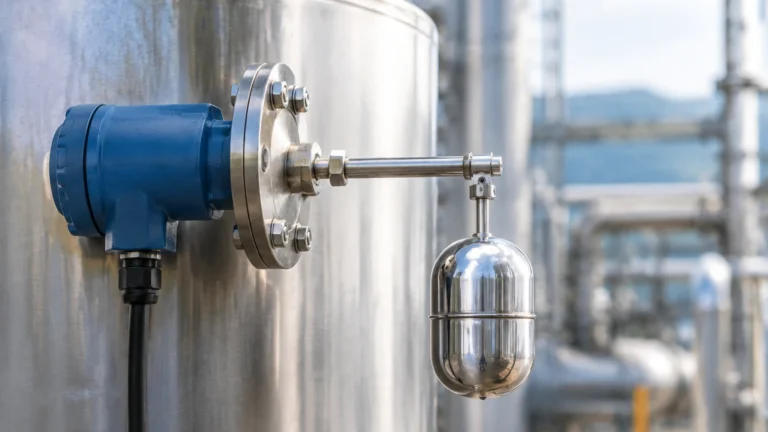
Magnetic level gauges provide both visual indication and point-level switching. A float containing a magnet moves with the liquid level, actuating external switches or a continuous transmitter. In SIS, these are often used as redundant high-high level alarms to trigger emergency shutdowns.
The Importance of Sis Functional Testing
Sis functional testing is a periodic activity required by international standards like IEC 61511 and IEC 61508. The goal is to detect "dangerous undetected" (DU) failures that the system’s internal diagnostics cannot identify.
For a level transmitter, a DU failure might include a frozen output signal, a fouled sensor face that reads a constant level regardless of actual liquid height, or a physical blockage in a stilling well. Functional testing involves simulating a high-level or low-level condition to ensure the logic solver receives the correct signal and the final element (such as a shutdown valve) moves to the safe position.
Proof Test Coverage (PTC)
The effectiveness of a test is measured by its Proof Test Coverage. A "comprehensive" test checks the entire loop from the sensor's physical interaction with the process to the final element's movement. A "partial" test might only check the electronics of the transmitter. In high-demand or high-risk scenarios, maximizing PTC is essential for maintaining the SIL rating.
Selection Criteria for SIS-Rated Level Instruments
Choosing the right instrument for a safety loop requires evaluating the process conditions against the instrument's capabilities. The following table provides a comparison of common technologies used in safety applications.
| Technology | SIL Suitability | Best For | Limitations | Maintenance Needs |
| :— | :— | :— | :— | :— |
| Guided Wave Radar | Up to SIL 3 | Low dielectric fluids, foam | Probe buildup | Periodic cleaning |
| Non-Contact Radar | Up to SIL 3 | Corrosive chemicals, high temp | Internal tank obstructions | Minimal |
| Ultrasonic | Up to SIL 2 | Water, wastewater, solids | Vacuum, high steam | Transducer cleaning |
| Hydrostatic | Up to SIL 2 | Vented tanks, consistent density | Density fluctuations | Diaphragm inspection |
| Magnetic Switch | Up to SIL 2 | High-level alarm redundancy | Mechanical wear, scaling | Float movement check |
When selecting equipment, engineers should Review product options and application support to ensure the chosen hardware meets the specific FM, CSA, or ATEX requirements of the installation site.
Installation Considerations for Safety Integrity
Proper installation is a prerequisite for successful sis functional testing. If an instrument is installed incorrectly, the test results may be misleading, or the instrument may fail prematurely.
1. Redundancy and Voting: Safety loops often use multiple sensors in a voting configuration (e.g., 1oo2, 2oo3). This ensures that a single sensor failure does not cause a nuisance trip or, more importantly, a failure to trip. During functional testing, each sensor must be tested individually to verify its contribution to the voting logic.
2. Separation: The SIS must be physically and logically separate from the Basic Process Control System (BPCS). Level transmitters used for safety should not be used for routine tank level control unless specific regulatory requirements for shared components are met.
3. Nozzle and Stilling Wells: For radar and ultrasonic sensors, the mounting nozzle must be free of internal burrs or obstructions that could cause false echoes. If a stilling well is used to dampen turbulence, it must be inspected for clogging during the functional test cycle.
4. Environmental Protection: In outdoor installations, sunshades and heaters may be necessary to prevent temperature extremes from affecting the electronics or causing condensation on the sensor face, which can lead to signal loss.

Step-by-Step Sis Functional Testing Procedure
A standard functional test for a level-based SIS loop typically follows these steps:
1. Preparation: Notify operations and bypass the safety loop if the plant is online (ensuring alternative safety measures are in place).
2. Visual Inspection: Check the instrument for physical damage, corrosion, or loose wiring.
3. Zero and Span Verification: Compare the instrument's reading against a secondary reference (e.g., a manual dip tape or a sight glass).
4. Simulation of Trip Point:
* Physical Method: Raise the actual liquid level in the tank to the trip point. This is the most thorough test.
* Substitution Method: Use a target board for radar or move the float for magnetic gauges.
* Electronic Method: Use a signal generator to simulate the 4-20mA or digital signal corresponding to the trip level. (Note: This has lower PTC as it does not test the physical sensing element).
5. Logic and Final Element Verification: Confirm that the logic solver recognizes the alarm and that the final control valve or pump moves to the safe state within the required response time.
6. Documentation: Record the results, including the "as-found" and "as-left" conditions, the date, and the personnel involved.
Limitations and Common Risks
While sis functional testing is vital, it is not without risks and limitations. Engineers must be aware of the following:
* Human Error: The most significant risk during testing is the failure to restore the system to its operational state. Leaving a loop in "bypass" mode after a test is a common cause of industrial accidents.
* Partial Testing Fallacy: Relying solely on electronic simulations can lead to a false sense of security. If the sensor's antenna is coated in hardened chemical buildup, an electronic test will pass, but the sensor will fail to detect a real high-level condition.
* Process Disturbance: Physical testing (filling the tank) can be difficult to manage without interrupting production or risking an actual spill if not monitored closely.
* Instrument Wear: Frequent mechanical testing of components like floats or valves can accelerate wear and tear, necessitating more frequent replacements.
Frequently Asked Questions (FAQs)
Q: How often should sis functional testing be performed?
A: The frequency is determined by the PFD calculation during the safety requirement specification (SRS) phase. It typically ranges from every six months to every few years, depending on the required SIL and the reliability of the components.
Q: Can I use the same level transmitter for control and safety?
A: Generally, no. Standards like IEC 61511 recommend separation to prevent a single failure from disabling both the control system and the safety system. If they are shared, the PFD calculation must account for the increased risk.
Q: What is the difference between a calibration and a functional test?
A: Calibration ensures the instrument is accurate across its range. A functional test (proof test) specifically verifies that the instrument will perform its safety function (e.g., triggering a shutdown) when the process reaches a dangerous limit.
Q: How do I handle testing for hazardous or toxic liquids?
A: In these cases, non-contact methods like radar are preferred. Testing is often done using "remote proof testing" capabilities built into modern smart transmitters, which can simulate a level change internally while verifying the health of the sensing circuit.
Conclusion
Effective sis functional testing is the cornerstone of industrial process safety. By understanding the underlying measurement principles—whether radar, ultrasonic, or hydrostatic—and implementing a rigorous testing schedule, facilities can significantly reduce the risk of catastrophic failures. Selecting high-quality, SIL-certified instrumentation and following best practices for installation and maintenance ensures that when a dangerous condition arises, the safety system will respond as designed. For further technical specifications and to explore reliable measurement hardware, engineers should visit the Main Page for comprehensive product data and engineering support.