Slope of Combustion Air Piping
Slope of Combustion Air Piping
In industrial combustion systems, the delivery of clean, dry air is fundamental to burner efficiency, equipment longevity, and operational safety. While much attention is paid to fuel-to-air ratios and burner head design, the physical layout of the intake system—specifically the slope of combustion air piping—is a critical engineering factor that is often overlooked until moisture-related failures occur. This guide examines the technical requirements for sloping combustion air lines, the physics of condensate formation, and the instrumentation used to monitor and manage these systems.
Measurement Principles in Combustion Air Systems
Before determining the physical layout of piping, it is essential to understand how process variables are measured within these environments. In combustion air systems, engineers must monitor flow rates, pressure, and the accumulation of liquids (condensate).
Level measurement plays a vital role in the safety of combustion systems. When air is drawn from the exterior or transported through long pipe runs, temperature differentials lead to condensation. If this liquid is not managed, it can lead to water hammer, burner flame-out, or corrosion. To manage this, condensate collection pots are installed at low points.
Welk utilizes several measurement principles for these applications:
1. Hydrostatic Pressure: This principle measures the pressure exerted by a column of liquid at the bottom of a collection tank. It is highly reliable for vented condensate pots where the density of the liquid (water) is known and constant.
2. Ultrasonic Level Sensing: This non-contact method uses sound waves to determine the distance to the liquid surface. It is ideal for applications where the liquid may be corrosive or where mechanical floats might fail due to debris.
3. Radar Level Measurement: For high-temperature or high-pressure environments, radar sensors provide millimeter-precision measurement by timing the flight of microwave pulses.
For a comprehensive overview of how these technologies integrate into industrial automation, you may visit our Main Page to review product options and application support.
The Technical Necessity of Slope
The primary reason for maintaining a specific slope of combustion air piping is the management of moisture. Air, particularly in humid or coastal environments, carries water vapor. As this air travels through piping that may be cooler than the air itself, the vapor reaches its dew point and transitions into a liquid state.
If the piping is perfectly horizontal, this liquid pools in the bottom of the pipe. Over time, these pools restrict airflow, increase static pressure, and can eventually be swept into the burner in large "slugs." A properly calculated slope ensures that gravity pulls this moisture toward a designated drainage point or condensate trap, keeping the main air stream dry.
Recommended Slopes and Engineering Standards
The industry standard for the slope of combustion air piping generally follows two main philosophies depending on the direction of the airflow and the location of the drainage points.
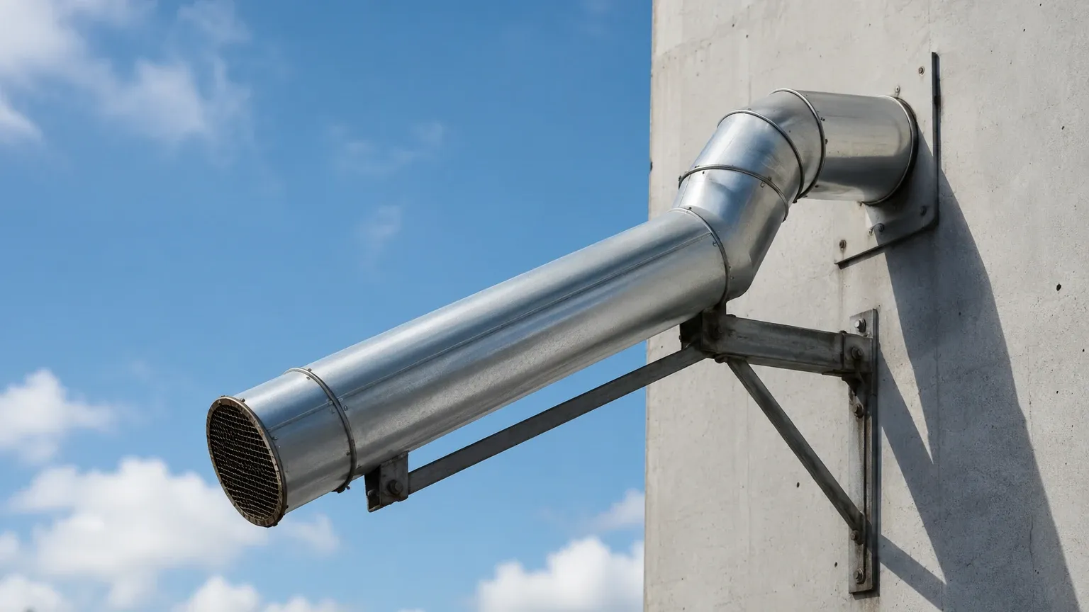
* Sloping Toward the Intake: In some configurations, the pipe is sloped back toward the exterior intake hood. This allows moisture to drain out of the system before it enters the building envelope. The recommended slope is typically 20 mm per meter (approximately 1/4 inch per foot).
* Sloping Toward a Condensate Trap: In most industrial settings, the piping is sloped toward a dedicated collection pot located near the burner or at the lowest point of the run. This prevents moisture from ever reaching the burner head. The standard slope here remains 20 mm per meter to ensure consistent drainage against the friction of the pipe wall.
| Pipe Material | Recommended Minimum Slope | Typical Application |
| :— | :— | :— |
| Carbon Steel (Smooth) | 1% (10 mm/m) | Indoor, temperature-controlled environments |
| Galvanized Steel | 2% (20 mm/m) | Standard industrial intake lines |
| PVC/CPVC | 1.5% (15 mm/m) | High-humidity or corrosive chemical environments |
| Stainless Steel | 1% (10 mm/m) | Food grade or high-purity combustion processes |
Selection Criteria for Condensate Monitoring
When designing the drainage system associated with the slope of combustion air piping, selecting the right level measurement instrument is crucial for automation. A collection pot that overflows is just as dangerous as a pipe with no slope.
1. Media Characteristics
Condensate in combustion air lines is primarily water, but it can contain dissolved gases (CO2, NOx) that make it slightly acidic. For these applications, stainless steel hydrostatic transmitters or plastic-bodied ultrasonic sensors are preferred to prevent chemical degradation.
2. Environmental Conditions
If the piping is located outdoors, the sensors must be rated for the local climate. This includes ingress protection (IP67 or IP68) and temperature compensation. In cold climates, the condensate pot must be heat-traced, and the level sensor must be able to operate accurately despite steam or frost formation.
3. Redundancy and Safety
In critical B2B industrial operations, such as power generation or large-scale steam production, a dual-point level switch system is often employed. A low-level switch triggers a drain valve, while a high-level switch triggers a system alarm or emergency shutdown to protect the burner from water ingestion.
Installation Considerations and Best Practices
Achieving the correct slope of combustion air piping requires more than just a calculation; it requires precise physical execution during the installation phase.
Pipe Support and Hanger Spacing
One of the most common failures in maintaining slope is "sagging." If pipe hangers are placed too far apart, the weight of the pipe (and any accumulated liquid) will cause the pipe to bow between supports. These bows create localized low points where water will trap regardless of the overall slope of the run. For standard 100 mm (4 inch) steel piping, supports should be placed every 2.5 to 3 meters.
Insulation Requirements
In many cases, sloping the pipe is not enough. If the temperature differential between the combustion air and the ambient environment is extreme, the rate of condensation may exceed the drainage capacity of a standard slope. Insulating the intake piping helps maintain the air temperature above the dew point for a longer duration, reducing the volume of liquid that the slope must manage.
Avoidance of U-Bends
Technicians must avoid any "traps" or U-bends in the piping layout. If a pipe must go down and then back up to clear an obstruction, a condensate collection pot and a level-monitored drainage system must be installed at that specific low point.
Common Risks and Limitations
Failure to adhere to the proper slope of combustion air piping leads to several documented industrial risks:
* Burner Instability: Moisture entering the combustion chamber can cause erratic flame patterns, leading to incomplete combustion and increased CO emissions.
* Corrosion Under Insulation (CUI): If moisture leaks from poorly sloped joints into the insulation, it can cause rapid, unseen corrosion of the pipe exterior.
* Sensor Interference: Flow meters located in the combustion air line (such as pitot tubes or thermal mass flow meters) are highly sensitive to moisture. Water droplets hitting these sensors will cause significant measurement errors, leading to improper fuel-air mixing.
* Freezing: In sub-zero environments, standing water in a poorly sloped pipe will freeze. This can partially or completely block the combustion air supply, leading to a dangerous rich-burn condition or a total system lockout.
Frequently Asked Questions (FAQ)
Q: Can I use a smaller slope if I have high-velocity airflow?
A: No. While high-velocity air can move some moisture, it often creates a "misting" effect where water is carried further into the system. A minimum 1% to 2% slope is always recommended regardless of air velocity to ensure drainage during periods of low demand or system standby.
Q: Where should the level sensor be placed in a condensate pot?
A: The sensor should be installed at the top of the collection pot, away from the direct path of the incoming drainage. This prevents turbulence from the falling water from causing false readings. If using a hydrostatic sensor, it should be mounted at the lowest point of the pot but protected from sediment buildup.
Q: How often should the slope be inspected?
A: The slope should be verified during the initial installation and after any significant seismic event or structural shift in the facility. Annual inspections should check for hanger integrity and signs of localized sagging.
Q: Is a slope required for vertical intake sections?
A: Vertical sections do not require a slope, but they must terminate in a T-junction with a collection leg at the bottom. This allows the air to turn horizontally while moisture continues to fall vertically into the trap.
Conclusion
Managing the slope of combustion air piping is a fundamental aspect of process engineering that ensures the reliability of industrial burners. By combining correct physical piping gradients with advanced level measurement technology, operators can automate moisture removal and protect their equipment from the costly effects of condensate. Whether utilizing hydrostatic, ultrasonic, or radar technology, the goal remains the same: ensuring that the air reaching the combustion zone is as dry and consistent as possible. For further technical specifications on the instruments used to monitor these critical systems, please refer to our Main Page for detailed product documentation.