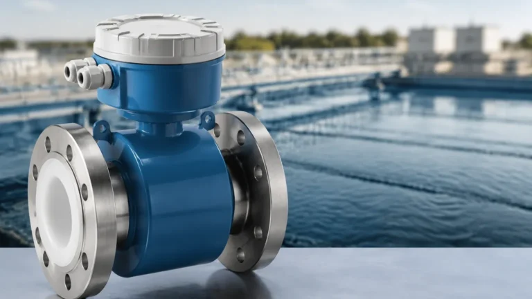
Ultrasonic Level Controller
Ultrasonic Level Controller
In the landscape of industrial automation and process control, the ultrasonic level controller represents a critical intersection of non-contact sensing technology and logic-driven management. These systems are essential for monitoring liquid and solid levels in tanks, pits, and silos across industries ranging from wastewater treatment to chemical processing. By utilizing high-frequency sound waves to determine the distance to a material surface, an ultrasonic level controller provides a reliable, maintenance-free alternative to mechanical float switches or invasive probes.
This guide provides a technical overview of ultrasonic measurement principles, system components, selection criteria, and installation best practices to assist engineers and procurement professionals in optimizing their level measurement strategies.
Understanding the Measurement Principle
The operation of an ultrasonic level controller is based on the "Time-of-Flight" (ToF) principle. The device’s transducer contains a piezoelectric crystal that converts electrical energy into mechanical pulses. These pulses are emitted as high-frequency sound waves (typically between 20 kHz and 200 kHz) toward the target material.
The Time-of-Flight Calculation
When the sound waves strike the surface of the medium, they are reflected back to the transducer. The controller’s electronics measure the time interval between the emission of the pulse and the reception of the echo. The distance is calculated using the following formula:
D = (c × t) / 2
Where:
* D is the distance from the sensor to the material surface.
* c is the speed of sound in the specific medium (usually air).
* t is the elapsed time for the round trip.
Since the total distance traveled includes the trip down and back, the result is divided by two. The controller then subtracts this distance from the known total height of the vessel to determine the actual level of the material.
Temperature Compensation
The speed of sound is significantly influenced by the temperature of the air through which it travels. In air, the speed of sound increases by approximately 0.6 meters per second for every degree Celsius increase in temperature. To maintain accuracy, modern ultrasonic level controllers incorporate an internal temperature sensor or an external probe to provide real-time compensation for these fluctuations.
Key Components of an Ultrasonic Level Control System
An industrial-grade ultrasonic level controller is typically composed of three primary functional blocks: the transducer, the signal processing electronics, and the control interface.
1. The Transducer: This is the "sensing head" of the instrument. It must be constructed from materials compatible with the environment, such as PVDF for corrosive chemicals or reinforced polymers for standard water applications. The design of the transducer determines the beam angle—the narrower the beam, the less likely it is to encounter interference from tank obstructions.
2. Signal Processing Electronics: Advanced controllers utilize Digital Signal Processing (DSP) to filter out "noise" or false echoes caused by internal tank structures like ladders, agitators, or weld seams. This is often referred to as False Echo Suppression or Echo Mapping.
3. The Controller and Output Interface: Unlike a simple transmitter that only sends a signal, a controller includes logic for managing external equipment. This includes built-in relays for pump control (start/stop), high/low-level alarms, and communication protocols such as 4-20mA HART, Modbus RS485, or Profibus. For comprehensive system integration, users can review product options and application support on the Main Page of the manufacturer’s technical portal.
Technical Selection Criteria for Industrial Applications
Selecting the correct ultrasonic level controller requires a detailed understanding of the application environment. A "one size fits all" approach often leads to measurement instability. The following table outlines the primary considerations for different model categories:
Selection Comparison Table
| Feature | Standard Liquid Model | Chemical/Corrosive Model | Long-Range Solids Model |
| :— | :— | :— | :— |
| Measurement Range | 0.25m to 5m | 0.3m to 10m | 0.6m to 30m |
| Transducer Material | ABS or PVC | PVDF or PTFE | Reinforced Polymer |
| Beam Angle | 10° – 12° | 8° – 10° | 5° – 8° |
| Operating Temp. | -20°C to +60°C | -40°C to +90°C | -40°C to +80°C |
| Pressure Rating | Atmospheric | Up to 3 Bar | Atmospheric |
| Typical Application | Water tanks, sumps | Acid storage, plating baths | Grain silos, ore bins |
Evaluation Factors
* The Dead Zone (Blocking Distance): Every ultrasonic sensor has a minimum distance near the transducer face where it cannot measure. This is caused by the time required for the crystal to stop vibrating after the pulse is sent. If the material enters this zone, the reading will be erratic or fixed at the maximum level.
* Beam Angle and Obstructions: A wider beam angle requires a clear path. If a tank has internal bracing, a narrow-beam transducer or a radar-based alternative might be necessary.
* Power Supply: Controllers are available in 2-wire (loop-powered) or 4-wire (separate power and signal) configurations. 4-wire models generally offer stronger pulse power, which is beneficial for dusty or turbulent environments.
Installation Best Practices and Geometric Considerations
Proper installation is the single most important factor in ensuring the longevity and accuracy of an ultrasonic level controller. Engineers should adhere to the following guidelines:
1. Positioning and Orientation
The transducer must be mounted perpendicular to the surface of the material being measured. If the sensor is tilted, the sound wave may bounce off the surface and hit the tank wall instead of returning to the sensor, resulting in signal loss. In liquid applications, the surface is generally flat, but in solids applications, the angle of repose must be considered.
2. Avoiding the "Wall Effect"
To prevent interference from the tank walls, the sensor should be mounted at a distance from the wall at least equal to 1/10th of the total tank height. Mounting too close to a wall can cause the sound wave to interact with the wall surface, creating false echoes that the DSP may struggle to filter.
3. Inflow and Turbulence
Never mount an ultrasonic level controller directly above the filling inlet. The falling stream of liquid or solid material will scatter the ultrasonic pulses and prevent them from reaching the actual level surface. If turbulence or splashing is present, a stilling well (a vertical pipe that dampens surface movement) may be required.
4. Mounting Nozzles
If the sensor is mounted on a nozzle or standpipe, the pipe must be smooth on the interior. The length of the nozzle should be kept as short as possible to ensure the transducer face extends into the tank, or at least remains clear of the nozzle's bottom edge, to avoid internal reflections.

Limitations and Environmental Constraints
While ultrasonic technology is versatile, it is not a universal solution. Certain physical conditions can attenuate or distort sound waves, leading to measurement failure.
* Foam and Aeration: Surface foam is one of the most common challenges. Heavy, dense foam acts as an acoustic absorber, soaking up the sound energy rather than reflecting it. In these cases, hydrostatic or radar measurement is preferred.
* Vacuum Conditions: Sound requires a medium (air or gas) to travel. Therefore, ultrasonic level controllers cannot function in a vacuum.
* High Pressure and Vapor: High-pressure environments change the density of the gas through which the sound travels, affecting the speed of sound beyond the capabilities of standard temperature compensation. Similarly, heavy vapors (like those from solvents) can change the gas composition, leading to significant errors.
* Dust and Powders: While ultrasonic sensors can measure solids, extremely fine dust in the air can attenuate high-frequency sound. For very dusty environments, lower-frequency transducers with high power output are necessary.
Maintenance and Troubleshooting FAQ
Q: How often does an ultrasonic level controller need calibration?
A: Unlike mechanical systems, ultrasonic sensors do not suffer from drift caused by wear. Calibration is typically performed once during commissioning. However, if the gas composition in the tank changes, the speed of sound constant must be updated.
Q: What causes the output to jump to the maximum value suddenly?
A: This is often a sign of "Loss of Echo." If the sensor cannot detect a return pulse (due to foam, extreme turbulence, or the level entering the dead zone), it may default to a fail-safe value. Checking the transducer face for condensation or buildup is the first troubleshooting step.
Q: Can I use an ultrasonic controller in a tank with an agitator?
A: Yes, provided the controller supports False Echo Suppression. You can program the controller to "ignore" the echoes at the specific distances where the agitator blades are located. However, the sensor should be positioned as far from the agitator shaft as possible.
Q: How do I handle condensation on the transducer?
A: Many industrial transducers feature a self-cleaning effect due to the vibration of the piezoelectric element. In high-humidity environments, choosing a model with a PTFE or hydrophobic face can help prevent water droplets from clinging to the sensor.
Conclusion: Selecting the Right Solution
The ultrasonic level controller remains a cornerstone of industrial level management due to its balance of cost, accuracy, and ease of use. By eliminating contact with the process media, these devices reduce maintenance overhead and prevent contamination. When specifying a system, engineers must weigh the physical properties of the media against the environmental constraints of the vessel.
For those requiring precise specifications, wiring diagrams, or specialized housing options for hazardous areas, consulting the Main Page of a dedicated manufacturer like Welk ensures access to the latest advancements in echo processing and transducer durability. Whether managing a simple water sump or a complex chemical reactor, the correct application of ultrasonic principles ensures a stable and efficient process control loop.