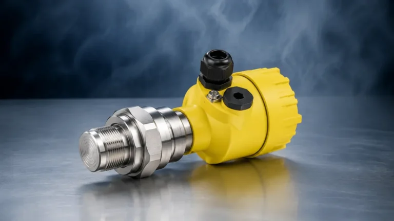
Steam Drum
Steam Drum
In industrial boiler systems, the steam drum serves as the primary interface between the water and steam phases. It is a critical pressure vessel located at the highest point of a water-tube boiler. Its primary functions are to separate steam from the water-steam mixture generated in the boiler tubes, store a reserve of water to accommodate load changes, and provide a location for chemical dosing and blowdown to manage water quality.
Accurate level measurement within a steam drum is not merely a matter of operational efficiency; it is a fundamental safety requirement. If the water level is too high (carryover), moisture can enter the steam turbines or downstream processes, causing catastrophic mechanical damage. If the level is too low (blow-dry), the boiler tubes may overheat and rupture due to a lack of cooling water. This guide explores the technical principles of level measurement in steam drums, selection criteria for instrumentation, and practical installation guidance.
Measurement Principles for Steam Drum Level
Measuring the level in a steam drum is uniquely challenging due to the high pressures, high temperatures, and the dynamic nature of the boiling process. Several technologies are commonly employed, each operating on different physical principles.
Hydrostatic Differential Pressure (DP)
Hydrostatic level measurement is the most traditional method used in steam drum applications. It relies on the principle that the pressure at the bottom of a liquid column is proportional to the height of that liquid and its density. In a steam drum, a differential pressure transmitter measures the difference between a "reference leg" (usually a wet leg filled with condensate) and the "variable leg" connected to the drum's water space.
Because the density of both water and steam changes significantly with pressure and temperature, DP systems require density compensation. Modern systems often integrate a pressure transmitter to provide real-time compensation factors to the flow computer or DCS (Distributed Control System).
Guided Wave Radar (GWR)
Guided Wave Radar uses high-frequency electromagnetic pulses transmitted along a probe (waveguide). When the pulse hits the water surface, a portion of the energy is reflected back to the transmitter due to the change in dielectric constant between the steam and the water. The time-of-flight determines the distance.
In high-pressure steam environments, the dielectric constant of the steam increases, which slows down the radar pulse. To maintain accuracy, GWR units used in steam drums often feature "Gas Phase Compensation" (GPC). This involves using a mechanical reference point on the probe at a known distance to calculate the actual speed of the pulse in the current steam conditions.
Magnetic Level Gauges (MLG)
Magnetic level gauges consist of a bypass chamber mounted to the side of the steam drum. Inside the chamber, a float containing a permanent magnet assembly rises and falls with the water level. Externally, a series of magnetic flags or a follower indicates the level visually. For electronic integration, a magnetostrictive transmitter or a series of reed switches can be strapped to the outside of the chamber. This provides a robust, non-contact electronic output while maintaining a local visual reference.
Conductivity Probes
Conductivity-based systems use multiple probes of varying lengths inserted into a vertical column. Water conducts electricity significantly better than steam. As the water level rises and touches a probe, an electrical circuit is completed. This technology is primarily used for discrete point level detection (High-High, High, Low, Low-Low alarms) and as a secondary validation for continuous measurement systems.
Key Evaluation Criteria for Instrumentation
Selecting the right instrumentation for a steam drum requires an analysis of the specific boiler design and operating parameters. Engineers must consider the following factors:
1. Operating Pressure and Temperature: Steam drums often operate at pressures exceeding 100 bar (1,450 psi) and temperatures above 310°C (590°F). All wetted materials and pressure-retaining components must be rated for these extremes.
2. Accuracy and Redundancy: Most regulatory codes (such as ASME Section I) require multiple independent level indications. A combination of a visual gauge and two or more electronic transmitters is standard practice.
3. Dynamic Response: During rapid load changes, the drum level can fluctuate quickly. The instrumentation must have a fast response time without being overly sensitive to surface turbulence.
4. Maintenance Requirements: Instruments with no moving parts, such as GWR or high-quality DP transmitters, generally offer lower long-term maintenance costs compared to mechanical floats in high-pressure service.
Practical Selection Table
The following table provides a comparison of common technologies used for steam drum level measurement.
| Technology | Accuracy | Pressure/Temp Resistance | Maintenance | Best Use Case |
| :— | :— | :— | :— | :— |
| Differential Pressure | High (with compensation) | Excellent | Moderate (Impulse lines) | Standard continuous control |
| Guided Wave Radar | Very High | Excellent (with GPC) | Low | High-pressure precision control |
| Magnetic Level Gauge | Moderate | High | Moderate (Float fouling) | Local visual + remote backup |
| Conductivity Probes | Discrete | Excellent | Low | Safety interlocks and alarms |
For a wider range of industrial measurement tools, engineers can Review product options and application support to find solutions tailored to specific boiler architectures.
Installation Considerations and Best Practices
The reliability of a steam drum level measurement is often determined more by the installation quality than the instrument itself.
Impulse Line Management
For DP transmitters, the impulse lines must be correctly sloped to prevent air pockets or unintended condensate traps. In steam service, a "wet leg" is usually preferred, where the reference line is kept full of condensate. Constant-head chambers are used to ensure the reference leg level remains stable despite fluctuations in drum pressure.
Insulation and Heat Tracing
While the steam drum itself is heavily insulated, the measurement legs or bypass chambers may require specific thermal management. If a magnetic level gauge or GWR chamber is uninsulated, the water inside may be significantly cooler than the water in the drum. This temperature difference causes a density mismatch, leading to a "false low" reading in the external chamber compared to the actual level inside the drum.
Stillwells and Bypass Chambers
Steam drums are turbulent environments. Using a stillwell (an internal pipe) or a bypass chamber (an external pipe) helps to dampen surface agitation and protect the sensor from the direct force of incoming feedwater or rising steam bubbles. This is particularly important for radar and float-based measurements.

Limitations and Common Risks
Engineers must be aware of the "Shrink and Swell" phenomena, which can lead to misleading level readings during transient states.
* Swell: When steam demand suddenly increases, the pressure in the drum drops slightly. This causes steam bubbles below the water line to expand, and more water to flash into steam. The result is a rapid rise in the apparent water level, even though the actual mass of water has not increased.
* Shrink: Conversely, when steam demand drops or cool feedwater is rapidly added, the steam bubbles collapse, and the water level appears to drop quickly.
Instrumentation must be calibrated and the control logic programmed to account for these physical behaviors to prevent unnecessary boiler trips. Furthermore, the buildup of magnetite or scale in bypass chambers can impede float movement or interfere with probe sensitivity, necessitating regular blowdown of the instrument legs.
Frequently Asked Questions (FAQs)
Q: Why is density compensation necessary for steam drum level?
A: At higher pressures, the density of liquid water decreases while the density of saturated steam increases. Since DP transmitters measure mass (pressure), they will under-read or over-read the physical height if the calculation does not account for the current operating pressure.
Q: Can I use ultrasonic sensors for steam drum level?
A: No. Ultrasonic sensors rely on sound waves, which are heavily affected by the temperature gradients, high pressure, and high-density steam found in a drum. The speed of sound changes too drastically in these conditions for reliable measurement.
Q: How often should steam drum level instruments be calibrated?
A: While electronic components are stable, the "system" (including impulse lines and chambers) should be checked during every major boiler turnaround. For DP transmitters, zero-checks should be performed more frequently, especially if the boiler undergoes frequent cycling.
Q: What is the benefit of using Guided Wave Radar over Differential Pressure?
A: GWR is a direct distance measurement and is less affected by the mechanical issues associated with impulse lines, such as leaks, clogging, or freezing. With Gas Phase Compensation, it can provide higher accuracy in high-pressure applications without the complex plumbing required for DP wet legs.
Conclusion
Effective management of a steam drum requires a deep understanding of both the physical properties of steam and the technical limitations of measurement hardware. By selecting robust technologies like those provided by Welk and adhering to strict installation standards, plant operators can ensure the safety and longevity of their boiler systems. For more detailed technical specifications on radar, ultrasonic, and hydrostatic sensors, visit the Main Page of our industrial measurement resource.