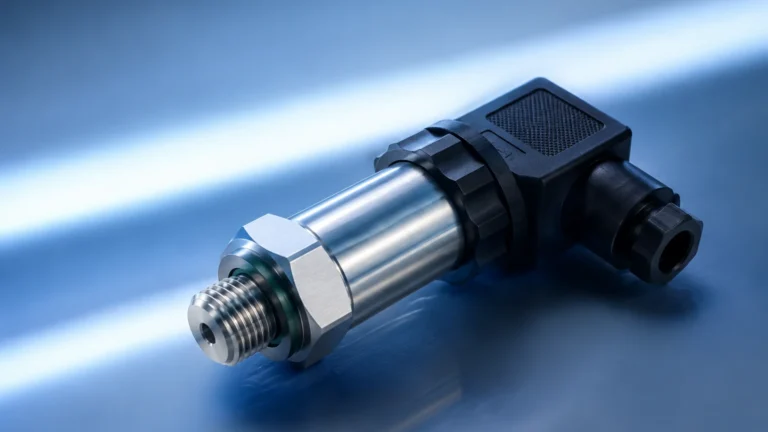
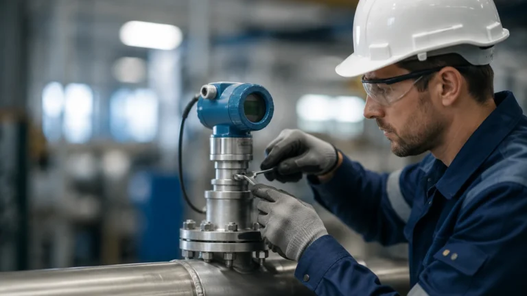
Submersible Pressure Transmitters
Submersible Pressure Transmitters
In the field of industrial automation and liquid management, submersible pressure transmitters represent one of the most reliable and cost-effective methods for continuous level measurement. These instruments, often referred to as hydrostatic level transmitters, are specifically engineered to be submerged directly into the process media. By measuring the pressure exerted by the liquid column above the sensor, they provide an accurate representation of the liquid level in applications ranging from deep-well groundwater monitoring to wastewater treatment and chemical storage.
As a professional manufacturer of industrial level measurement instruments, Welk provides a range of solutions designed to meet the rigorous demands of modern industry. Understanding the underlying physics, selection criteria, and installation best practices is essential for engineers and plant managers seeking to optimize their processes.
Measurement Principle: The Physics of Hydrostatics
The operation of submersible pressure transmitters is based on the principle of hydrostatic pressure. In a stationary liquid, the pressure at any given depth is directly proportional to the height of the liquid column above that point, the density of the liquid, and the force of gravity.
The mathematical formula used to calculate this is:
P = ρ × g × h
Where:
* P is the hydrostatic pressure (measured by the transmitter).
* ρ (Rho) is the density of the liquid (e.g., 1,000 kg/m³ for water).
* g is the acceleration due to gravity (approximately 9.81 m/s²).
* h is the height of the liquid column (the level being measured).
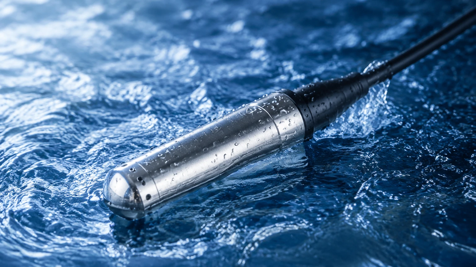
Because gravity is constant and the density of most liquids remains relatively stable under consistent temperatures, the pressure measured by the sensor correlates directly to the depth. Submersible pressure transmitters utilize a sensing element—typically a piezoresistive silicon chip or a ceramic diaphragm—to detect this pressure. The sensor converts the mechanical pressure into an electrical signal (usually 4-20mA or a digital protocol like RS485 Modbus), which is then transmitted via a specialized cable to a control system or display.
Atmospheric Pressure Compensation
A critical aspect of submersible level measurement is the need to compensate for changes in atmospheric pressure. Since the liquid surface is exposed to the atmosphere, the total pressure at the bottom of a tank is the sum of the hydrostatic pressure and the ambient air pressure. To ensure the transmitter only measures the pressure of the liquid column, a small vent tube is integrated into the core of the submersible cable. This tube allows the back of the sensing diaphragm to "breathe," effectively canceling out the atmospheric pressure acting on the liquid surface.
Key Components and Construction
To withstand continuous immersion in potentially corrosive or abrasive environments, submersible pressure transmitters are constructed with high-grade materials and robust sealing technologies.
1. The Sensor Head: Usually housed in 304 or 316L stainless steel, the head contains the sensing element and the signal conditioning electronics. For highly corrosive media, materials like Hastelloy, Tantalum, or PTFE coatings are employed.
2. The Diaphragm: This is the interface between the liquid and the electronics. It must be flexible enough to detect minute pressure changes but durable enough to resist deformation or chemical attack.
3. The Submersible Cable: This is more than just a wire; it is a critical component of the instrument. It includes the electrical conductors, the atmospheric vent tube, and a high-strength tensile member (such as Kevlar) to prevent stretching under the weight of the sensor in deep-well applications. Common jacket materials include Polyurethane (PUR), Polyethylene (PE), or Fluorinated Ethylene Propylene (FEP).
4. The Seal: Multi-stage sealing, often involving O-rings and epoxy potting, ensures that the internal electronics remain dry (IP68 rating).
Practical Selection Criteria
Choosing the right submersible pressure transmitter requires a thorough evaluation of the application's physical and chemical parameters. The following table provides a high-level comparison of common selection factors:
Selection Matrix for Submersible Transmitters
| Criteria | Standard Water Application | Wastewater/Sludge | Corrosive Chemicals |
| :— | :— | :— | :— |
| Housing Material | 304 or 316L Stainless Steel | 316L Stainless Steel | PTFE, PVDF, or Hastelloy |
| Diaphragm Type | Stainless Steel | Flush/Non-clogging Ceramic | Tantalum or Ceramic |
| Cable Jacket | Polyurethane (PUR) | Polyethylene (PE) | FEP or PTFE |
| Accuracy | 0.5% FS | 0.5% – 1.0% FS | 0.25% – 0.5% FS |
| Pressure Range | 0-5m to 0-200m H2O | 0-2m to 0-20m H2O | Application Specific |
Detailed Evaluation Factors
* Measurement Range: It is vital to select a transmitter with a range that closely matches the maximum depth of the tank or well. While a 100m sensor can measure 5m of water, the accuracy (expressed as a percentage of Full Scale) will be significantly lower than a sensor designed specifically for a 5m range.
* Media Density: If the liquid being measured is not water (e.g., diesel fuel or concentrated brine), the density must be accounted for in the calibration of the transmitter or the configuration of the PLC/display unit.
* Temperature Range: Standard sensors typically operate between -20°C and +80°C. High-temperature variants are available, but extreme heat can affect the density of the liquid and the stability of the electronics.
* Output Signal: In most industrial environments, a 4-20mA current loop is preferred due to its resistance to electrical noise over long cable runs. For smart city or remote monitoring applications, RS485 Modbus or low-power wireless outputs may be more appropriate.
Installation Considerations and Best Practices
Proper installation is the single most important factor in ensuring the longevity and accuracy of submersible pressure transmitters. Even the highest quality sensor will fail or provide erratic data if installed incorrectly.
1. Avoiding Turbulence
In tanks with agitators or near high-flow inlet pipes, the moving liquid can cause physical movement of the sensor or localized pressure fluctuations (dynamic pressure). To mitigate this, the sensor should be installed inside a "stilling well"—a vertical pipe with small holes that allows the liquid level to equalize while shielding the sensor from turbulence.
2. Cable Management
The submersible cable should be securely anchored at the top of the vessel or well. Use a specialized cable clamp that provides a firm grip without crushing the internal vent tube. If the vent tube is blocked or kinked, the transmitter will no longer compensate for atmospheric pressure, leading to significant measurement errors.
3. Protecting the Vent Tube
The end of the vent tube (located at the dry end of the cable) must be kept clean and dry. Moisture entering the vent tube can travel down to the sensor head and cause internal corrosion or electrical shorts. It is highly recommended to use a desiccant box or a specialized breathable vent filter at the cable termination point.
4. Lightning and Surge Protection
In outdoor applications, such as reservoirs or deep wells, the long cable acts as an antenna for electrical surges. Ensure the transmitter has built-in surge protection and that the system is properly grounded according to the manufacturer's specifications.
Limitations of Submersible Pressure Transmitters
While highly versatile, hydrostatic measurement is not suitable for every scenario. Engineers should be aware of the following limitations:
* Variable Density: If the density of the liquid changes frequently (e.g., due to significant temperature swings or mixing of different chemicals), the level reading will drift unless the system includes a second sensor for density compensation.
* Pressurized Vessels: Submersible transmitters are designed for vented tanks. In a pressurized tank, the sensor would measure the sum of the liquid pressure and the overhead gas pressure, resulting in an incorrect level reading. In these cases, a differential pressure transmitter is required.
* Sediment and Buildup: In wastewater applications, heavy sludge or debris can settle on the diaphragm. Regular cleaning or the use of a flush-diaphragm design is necessary to prevent clogging.
Comparison with Alternative Technologies
To provide context for selection, it is helpful to compare submersible transmitters with other common level measurement technologies found on the Main Page of industrial instrumentation catalogs.
| Feature | Submersible Pressure | Ultrasonic (Non-contact) | Radar (Non-contact) |
| :— | :— | :— | :— |
| Installation | Direct Immersion | Top-mounted | Top-mounted |
| Vapor/Foam | Unaffected | High Interference | Minimal Interference |
| Moving Parts | None | None | None |
| Cost | Low to Moderate | Moderate | High |
| Maintenance | Periodic Cleaning | Low | Very Low |
| Best For | Deep wells, clear liquids | Open channels, sumps | Corrosives, high precision |
Frequently Asked Questions (FAQs)
Q: How do I calibrate a submersible pressure transmitter?
A: Most units are factory-calibrated. However, field zeroing can be performed by lifting the sensor out of the liquid and ensuring the output is 4mA (or 0 bar). Full calibration requires a pressure calibrator or comparing the output against a known physical depth measurement.
Q: Can I cut the submersible cable to length?
A: Yes, the cable can usually be shortened, but extreme care must be taken not to damage the internal vent tube. Always re-terminate the cable using the manufacturer’s recommended junction box to maintain the integrity of the atmospheric vent.
Q: How often should the sensor be cleaned?
A: This depends entirely on the media. In clean water, a sensor may last years without maintenance. In wastewater, a monthly or quarterly inspection is recommended to check for biological growth or sediment buildup on the diaphragm.
Q: What is the maximum depth these sensors can measure?
A: Standard industrial models typically handle up to 200 meters (approx. 20 bar), but specialized deep-well versions can reach depths of 500 meters or more, provided the cable is reinforced to handle the weight.
Conclusion
Submersible pressure transmitters are a cornerstone of modern level measurement due to their simplicity, reliability, and ease of integration. By converting hydrostatic pressure into a precise electrical signal, they allow for effective monitoring of critical water and chemical resources. When selecting a device, engineers must prioritize material compatibility and proper installation techniques—particularly regarding the atmospheric vent tube—to ensure long-term performance.
For those evaluating specific hardware for water treatment, industrial automation, or chemical processing, it is essential to consult with a provider that offers customized OEM/ODM services and strict quality control. For a comprehensive review of product options and application support, visit the Main Page to explore the full range of level measurement solutions available for global industrial needs.