Supplementary Notebook
Supplementary Notebook
In the complex landscape of industrial process control, the accuracy of level measurement is rarely the result of a single instrument's performance alone. Instead, it is the product of precise engineering, environmental analysis, and meticulous documentation. A supplementary notebook serves as the critical bridge between theoretical sensor specifications and the practical realities of the field. For engineers and site managers, this documentation acts as a repository for site-specific variables—such as dielectric constants, vapor pressures, and physical tank obstructions—that dictate the success or failure of a level measurement installation.
To effectively utilize a supplementary notebook in a B2B industrial context, one must first understand the underlying physics of the instruments being deployed. Whether managing water treatment facilities or chemical processing plants, the choice of technology must be grounded in the fundamental principles of measurement.
Fundamental Principles of Level Measurement
Before selecting an instrument or recording its parameters in a supplementary notebook, it is essential to understand how different technologies interact with the process media.
Radar Level Measurement (ToF)
Radar level meters operate on the Time-of-Flight (ToF) principle. The device emits a high-frequency electromagnetic wave (typically in the GHz range) that travels to the surface of the medium, reflects, and returns to the sensor. Because electromagnetic waves travel at the speed of light, the instrument calculates the distance based on the nanosecond time interval between emission and reception.
* Guided Wave Radar (GWR): Uses a physical probe (rod or cable) to direct the signal. This is ideal for low dielectric liquids or environments with heavy foam.
* Non-Contact Radar: Emits signals through the air. It is preferred for corrosive media or applications where the sensor cannot touch the product.
Ultrasonic Level Sensors
Ultrasonic sensors use mechanical sound waves rather than electromagnetic waves. The sensor pulses an ultrasonic sound wave (usually 20 kHz to 200 kHz) toward the target. The time taken for the echo to return is proportional to the distance. Unlike radar, the speed of sound is heavily influenced by air temperature and gas composition, requiring integrated temperature compensation for accuracy.
Hydrostatic Level Transmitters
This technology relies on the principle that the pressure at the bottom of a liquid column is directly proportional to the height of the liquid and its specific gravity ($P = \rho \cdot g \cdot h$). By measuring the head pressure, the transmitter can determine the level, provided the density of the fluid remains constant.
Magnetic Level Gauges
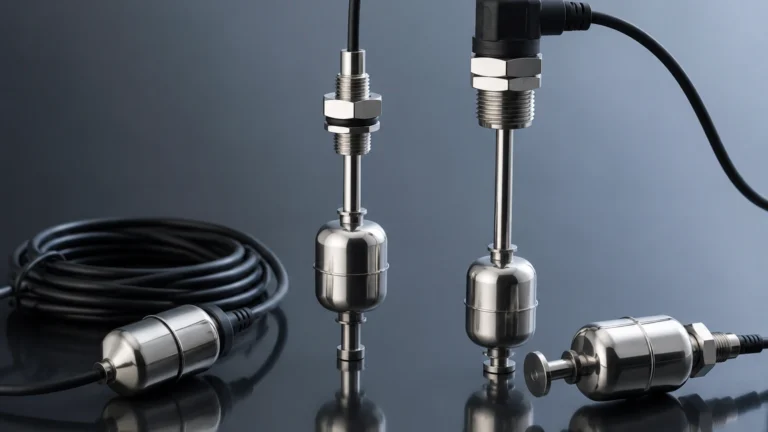
Magnetic gauges utilize the principle of buoyancy and magnetic coupling. A float containing a permanent magnet moves with the liquid level inside a bypass chamber. Outside the chamber, magnetized flaps or a follower indicate the level. This is a purely mechanical and highly visual method, often used as a redundant check for electronic systems.
The Role of the Supplementary Notebook in Field Engineering
In professional level measurement, a supplementary notebook is more than a simple log; it is a technical record of the "as-installed" environment. While a manufacturer's Main Page provides the standard operating ranges, the notebook captures the nuances of the specific application.
Data to Record in the Supplementary Notebook
1. Dielectric Constant ($ε_r$): For radar applications, the reflectivity of the surface depends on the dielectric constant. Recording this value helps in fine-tuning signal thresholds.
2. Vapor Space Composition: Changes in gas density or the presence of heavy vapors can attenuate ultrasonic signals or slightly shift radar velocity.
3. Agitation and Turbulence: Notes on the frequency and intensity of agitators help in configuring software filters (false echo suppression).
4. Nozzle Dimensions: The height and diameter of the mounting nozzle can create "ringing" or parasitic reflections that must be mapped out during commissioning.
Selection Criteria and Technical Comparison
Choosing the right technology requires balancing cost, accuracy, and environmental constraints. The following table provides a reference for the selection process commonly documented in a supplementary notebook.
| Technology | Typical Accuracy | Max Range | Media Constraints | Ideal Applications |
| :— | :— | :— | :— | :— |
| Radar (80GHz) | ±1 mm | Up to 120m | High temp/pressure; ignore dust | Chemical reactors, tall silos |
| Ultrasonic | ±0.25% of range | Up to 30m | Sensitive to foam/vacuum | Water tanks, open channels |
| Hydrostatic | ±0.1% to 0.5% | Varies by pressure | Requires constant density | Deep wells, fuel storage |
| Magnetic Gauge | ±5 mm to 10 mm | Up to 6m | Clean liquids only | Boiler drums, oil tanks |
Installation Considerations and Best Practices
Proper installation is the most significant factor in instrument longevity. When documenting an installation in a supplementary notebook, engineers must verify several physical parameters.
Beam Angle and Obstructions
Every non-contact sensor has a beam angle (e.g., 3° to 10°). The "footprint" of the signal expands as it travels deeper into the tank. It is vital to ensure that the signal path is clear of ladders, heating coils, or inflow streams. If an obstruction is unavoidable, "False Echo Mapping" must be performed and recorded in the notebook to tell the sensor to ignore those specific reflections.
The Dead Zone (Blocking Distance)
All sensors have a minimum distance they cannot measure, known as the dead zone or blocking distance. For ultrasonic sensors, this is usually 0.2m to 0.5m. For radar, it can be as small as 50mm. The supplementary notebook should clearly state the maximum fill level to prevent the media from entering this zone, which would cause the sensor to lose its signal or provide erratic readings.
Mounting Orientation
* Radar/Ultrasonic: Must be mounted perpendicular to the liquid surface to ensure the signal reflects directly back to the transducer.
* Hydrostatic: Should be mounted at the lowest point of the vessel, avoiding areas of high turbulence (like near a pump intake) which can cause pressure fluctuations.

Limitations and Common Risks
Even the most advanced instruments have limitations that must be acknowledged in the project's supplementary notebook to prevent operational failure.
1. Foam Interference: Heavy, dense foam can absorb ultrasonic and radar signals. In such cases, guided wave radar or hydrostatic transmitters are often the only reliable alternatives.
2. Vacuum Environments: Ultrasonic waves cannot travel through a vacuum. Radar is unaffected by vacuum but may require specialized seals for high-pressure transitions.
3. Coating and Buildup: In sticky or viscous media, material buildup on the sensor face or probe can cause signal loss. Regular maintenance intervals for cleaning should be scheduled based on the notes in the supplementary notebook.
4. Temperature Gradients: Rapid temperature changes in the vapor space can cause condensation on the sensor face. Using a PTFE-faced antenna or a purging system can mitigate this risk.
Frequently Asked Questions (FAQ)
Q: Why is my radar sensor showing a full tank when it is actually empty?
A: This is often caused by a strong reflection from the mounting nozzle or an internal obstruction (like a ladder) being misinterpreted as the product level. Check your supplementary notebook for the original "Empty Map" or "False Echo Suppression" settings and recalibrate if the tank internals have changed.
Q: Can I use an ultrasonic sensor in a pressurized vessel?
A: Generally, no. Ultrasonic sensors are designed for atmospheric or near-atmospheric conditions. High pressure changes the density of the air, which significantly alters the speed of sound, leading to large measurement errors. Radar is the preferred non-contact solution for pressurized tanks.
Q: How often should I calibrate my level meters?
A: Calibration frequency depends on the criticality of the process and the stability of the media. For water applications, an annual check is often sufficient. For corrosive chemical processes, a quarterly verification against a manual dip-tape or a magnetic gauge is recommended, with results documented in the supplementary notebook.
Conclusion
Reliable level measurement is the cornerstone of industrial safety and efficiency. By combining high-quality instrumentation with a disciplined approach to documentation—exemplified by the use of a supplementary notebook—operators can ensure their systems remain accurate over years of service. For those seeking to explore specific hardware options, including radar, ultrasonic, and magnetic solutions, the Main Page of the manufacturer provides the technical datasheets and application support necessary to begin the selection process. Always remember that the instrument is only as good as the data used to configure it; keep your field notes precise, your calibrations current, and your installation environment well-mapped.