Tank Level Controller
Tank Level Controller
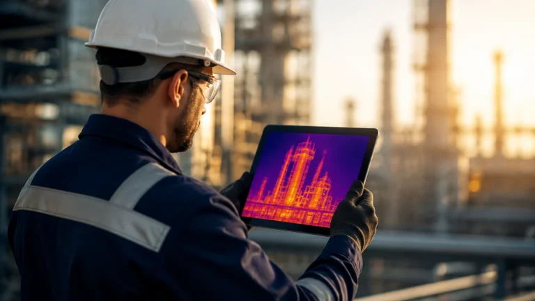
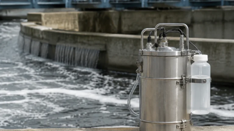
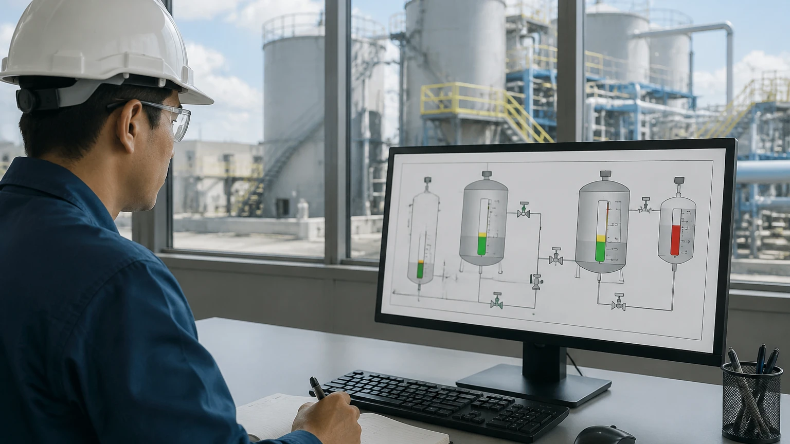
In modern industrial processing, the tank level controller serves as the central intelligence for liquid management. Whether managing municipal water reservoirs, chemical storage tanks, or oil-water separators, these systems ensure that levels remain within safe operational parameters while optimizing pump efficiency and preventing costly overflows or dry-run conditions. A tank level controller is not a single component but a coordinated system consisting of a sensing element (transmitter), a processing unit (controller), and final control elements such as valves or pumps.
Selecting the correct technology requires a deep understanding of the physical principles of measurement, the chemical properties of the media, and the mechanical constraints of the vessel. This guide provides an engineering-focused overview of how to evaluate and implement effective level control solutions.
Principles of Level Measurement
Before a tank level controller can execute logic, it must receive accurate data from a level sensor. Industrial sensors generally fall into two categories: continuous measurement and point level detection. Continuous sensors provide a real-time signal (typically 4-20mA or RS485) representing the exact level, while point level switches indicate when a specific threshold has been reached.
Radar Level Measurement
Radar transmitters utilize high-frequency electromagnetic waves, typically in the 26GHz or 80GHz range. In non-contact radar, the device emits a signal that reflects off the surface of the liquid and returns to the sensor. The controller calculates the distance based on the Time-of-Flight (ToF).
* Advantages: Highly accurate (up to ±1mm), unaffected by vacuum, pressure, or temperature fluctuations, and capable of measuring through steam or dust.
* Best For: Corrosive chemicals, high-temperature oil storage, and large-scale silos.
Ultrasonic Level Measurement
Ultrasonic sensors emit acoustic pressure waves that reflect off the liquid surface. Like radar, they use ToF to determine the level. However, because sound requires a medium (air) to travel, the accuracy can be influenced by changes in air temperature, humidity, and heavy foam.
* Advantages: Cost-effective, non-contact, and easy to install in open-air applications.
* Best For: Water treatment plants, wastewater sumps, and atmospheric storage tanks.
Hydrostatic Pressure Measurement
This principle relies on the relationship between the height of a liquid column and the pressure it exerts at the base of the tank. The formula $P = \rho gh$ (where $P$ is pressure, $\rho$ is density, $g$ is gravity, and $h$ is height) allows the tank level controller to translate pressure readings into precise level data.
* Advantages: Simple to maintain, excellent for deep wells or vented tanks, and highly reliable for clean liquids.
* Best For: Borehole monitoring, fuel tanks, and water towers.
Magnetic Level Gauges
Magnetic gauges utilize a float containing a permanent magnet that moves with the liquid level. This float interacts with an external indicator or a reed-chain transmitter. This provides both a local visual reference and an electronic signal for the controller.
* Advantages: No power required for visual indication, safe for flammable liquids, and highly durable in high-pressure environments.
* Best For: Boiler drums and high-pressure oil/gas separators.
Controller Logic and Integration
The tank level controller unit receives the signal from the sensors mentioned above and performs specific logic functions. In B2B industrial environments, this is often handled by a dedicated digital controller or integrated into a Distributed Control System (DCS).
1. On/Off Control (Hysteresis): The most basic form of control used for pump-up or pump-down applications. The controller turns a pump on at a low setpoint and off at a high setpoint to prevent frequent motor cycling.
2. PID Control: For processes requiring a constant level despite varying inflow or outflow, Proportional-Integral-Derivative (PID) logic modulates a control valve to maintain a precise "setpoint."
3. Alarm Management: Controllers are configured with High-High (HH), High (H), Low (L), and Low-Low (LL) alarms to trigger emergency shutdowns or notify operators of potential issues.
4. Communication Protocols: Modern controllers often support Modbus RTU, HART, or Profibus, allowing for seamless integration into the facility’s automation architecture. For detailed specifications on compatible hardware, you can review product options and application support on our Main Page.
Selection Criteria for Industrial Applications
Choosing the right tank level controller system involves balancing technical requirements with budget constraints. The following table summarizes the primary considerations for the most common industrial technologies.
Practical Selection Table
| Technology | Typical Accuracy | Max Range (Metric/Imperial) | Media Compatibility | Relative Cost |
| :— | :— | :— | :— | :— |
| 80GHz Radar | ±1 mm | 120m (393 ft) | Corrosives, Slurries, Hydrocarbons | High |
| Ultrasonic | ±0.25% FS | 15m (49 ft) | Water, Dilute Acids, Bases | Low-Medium |
| Hydrostatic | ±0.5% FS | 200m (656 ft) | Clean Liquids, Water, Oils | Medium |
| Magnetic Gauge | ±5 mm | 6m (20 ft) | Flammable, High-Pressure Liquids | Medium-High |
| Level Switch | N/A (Point) | N/A | Solids, Liquids, Interface | Low |
Installation Considerations and Best Practices
Even the most advanced tank level controller will fail if the sensing element is improperly installed. Engineers should adhere to the following guidelines:
* Avoid the Fill Stream: Never install a sensor directly above the inlet pipe. The turbulence and falling liquid will create false echoes for radar and ultrasonic sensors or cause erratic pressure readings for hydrostatic sensors.
* Dead Zone (Blocking Distance): Ultrasonic and radar sensors have a "dead zone" near the antenna where measurements are impossible. Ensure the sensor is mounted high enough that the maximum liquid level never enters this zone.
* Obstruction Clearance: For non-contact sensors, the signal spreads in a cone shape. Ensure there are no internal tank structures (ladders, agitators, or heating coils) within the signal's path. A clear 15° to 20° cone is typically required.
* Stilling Wells: In tanks with heavy agitation or surface foam, installing the sensor inside a stilling well (a vertical pipe) can provide a stable surface for measurement.
* Venting: For hydrostatic transmitters, ensure the tank is either vented to the atmosphere or use a differential pressure transmitter to account for the vapor space pressure.
Limitations and Common Risks
While industrial level controllers are robust, certain environmental factors can introduce risks:
* Foam and Turbulence: Heavy foam can absorb ultrasonic signals, leading to a "Loss of Echo" error. In these cases, 80GHz radar or hydrostatic sensors are preferred.
* Dielectric Constant (Dk): Radar sensors rely on the dielectric constant of the liquid to reflect the signal. Liquids with a very low Dk (like some liquefied gases) may require guided wave radar (GWR) to ensure signal return.
* Build-up and Scaling: In wastewater or cement applications, material can build up on the sensor face. Non-contact sensors are less prone to this, but regular maintenance is still required to ensure the lens or transducer remains clean.
* Temperature Extremes: High temperatures can cause signal drift in electronics. Always check the operating temperature range of the transmitter and use cooling fins or remote electronics if necessary.
Frequently Asked Questions (FAQ)
Q: Can one tank level controller manage multiple tanks?
A: Yes, many multi-channel digital controllers can accept inputs from 4 to 8 different transmitters and provide independent relay outputs for each tank.
Q: What is the difference between a level transmitter and a level switch?
A: A transmitter provides a continuous signal (e.g., 0-100% full), whereas a switch only provides a binary signal (on/off) when the liquid reaches a specific point.
Q: How often should a tank level controller be calibrated?
A: For non-critical water storage, annual calibration is usually sufficient. For high-accuracy chemical dosing or custody transfer of fuels, semi-annual or quarterly calibration is recommended.
Q: Is radar better than ultrasonic for all applications?
A: Not necessarily. While radar is more versatile, ultrasonic sensors are significantly more affordable and perfectly adequate for simple water level monitoring where no steam or high pressure is present.
Conclusion
Implementing a reliable tank level controller system is a critical step in ensuring process safety and operational efficiency. By understanding the underlying physics of radar, ultrasonic, and hydrostatic measurement, and by following strict installation protocols, engineers can minimize downtime and prevent environmental hazards.
When specifying a system, always confirm the chemical compatibility of the wetted materials, the required accuracy for your specific process, and the integration requirements of your existing control network. For further technical guidance and to view our full range of industrial measurement solutions, visit our Main Page.