Tank Monitor System
Tank Monitor System
In modern industrial environments, a tank monitor system serves as the central nervous system for liquid and solid inventory management. Beyond simple level detection, these integrated solutions provide the data necessary for operational safety, regulatory compliance, and supply chain optimization. Whether managing volatile chemicals, wastewater, or bulk solids, selecting the appropriate monitoring architecture requires a deep understanding of measurement physics, sensor technology, and data integration protocols.
A professional tank monitor system typically comprises three primary layers: the field sensing element, the signal transmission interface, and the data visualization or control platform. For engineers and facility managers, the challenge lies in matching the specific physical properties of the stored media with a technology that can withstand the environmental rigors of the application. As a specialized manufacturer, Welk provides a range of instruments designed to bridge the gap between raw field data and actionable industrial intelligence.
Core Measurement Principles and Technologies
Before implementing a tank monitor system, it is essential to evaluate the measurement principle best suited for the vessel’s contents. No single technology is universal; each possesses distinct advantages and inherent physical limitations.
Radar Level Measurement (FMCW and Pulse)
Radar technology is widely considered the gold standard for high-accuracy industrial applications. It operates on the Time-of-Flight (ToF) principle, where electromagnetic pulses are emitted toward the product surface and reflected back to the sensor.
Modern systems often utilize Frequency Modulated Continuous Wave (FMCW) radar, typically operating at 26GHz or 80GHz. The 80GHz variants offer a narrower beam angle, which is critical for avoiding internal tank obstructions like agitators, ladders, or heating coils. Because radar waves do not require a medium for travel, they are unaffected by vacuum, high pressure, or temperature fluctuations, making them ideal for complex chemical reactors and oil storage.
Ultrasonic Level Sensors
Ultrasonic sensors function by emitting high-frequency sound waves. The system measures the time interval between the emission of the sound and the reception of the echo. While cost-effective and reliable for many water treatment and open-channel applications, ultrasonic technology is sensitive to the composition of the air space. Factors such as heavy vapors, high dust concentrations, or significant temperature gradients can alter the speed of sound, leading to measurement errors unless properly compensated.
Hydrostatic Pressure Transmitters
Hydrostatic monitoring relies on the relationship between the height of a liquid column and the pressure it exerts at the base of the tank. The formula $P = \rho \cdot g \cdot h$ (where $P$ is pressure, $\rho$ is density, $g$ is gravity, and $h$ is height) allows the system to calculate the level based on the weight of the fluid. This method is highly effective for vented tanks and constant-density liquids. However, if the density of the liquid changes due to temperature or chemical composition, the system requires recalibration or secondary compensation.
Magnetic Level Gauges and Switches
For high-pressure or hazardous environments where a visual indication is required alongside electronic monitoring, magnetic level gauges are used. A float containing a permanent magnet moves with the liquid level inside a bypass chamber, flipping external flags for visual tracking and actuating reed switches or transmitters for remote data logging. This mechanical-electronic hybrid provides a fail-safe redundant monitoring method.
Practical Selection Criteria for Industrial Applications
Choosing the components for a tank monitor system requires a systematic review of the process conditions. Engineers should use the following criteria to narrow down technology options:
1. Media Characteristics: Is the material corrosive, viscous, or prone to coating? Radar is preferred for corrosive media as non-contact versions prevent sensor degradation. For thick slurries, hydrostatic sensors with flush diaphragms may be necessary to prevent clogging.
2. Tank Geometry: Tall, narrow silos benefit from the focused beam of 80GHz radar. Conversely, shallow sumps are often adequately served by ultrasonic sensors.
3. Process Environment: High-pressure vessels (exceeding 40 bar / 580 psi) or extreme temperatures (above 200°C / 392°F) typically necessitate specialized radar or magnetic gauge configurations.
4. Accuracy Requirements: For custody transfer or high-value chemical inventory, a high-precision radar system with ±1mm (0.04 in) accuracy is standard. For general process control, ±5mm to ±10mm may be sufficient.
Technology Comparison Table
| Technology | Contact Type | Ideal Media | Max Range (Typical) | Relative Cost | Key Limitation |
| :— | :— | :— | :— | :— | :— |
| 80GHz Radar | Non-contact | Chemicals, Oils, Solids | 30m – 120m | High | Dielectric constant (εr) > 1.4 |
| Ultrasonic | Non-contact | Water, Wastewater | 15m – 30m | Low/Medium | Affected by foam and heavy vapor |
| Hydrostatic | Contact | Liquids in vented tanks | 20m (Head) | Medium | Requires constant density |
| Magnetic Gauge| Contact | Hazardous Liquids | 6m | Medium/High | Moving parts subject to wear |
Installation Best Practices and Geometric Considerations
A tank monitor system is only as accurate as its installation. Even the most advanced sensor will fail if placed incorrectly relative to the tank's internal dynamics.
Nozzle and Mounting Position
The sensor should generally be mounted at 1/3 of the tank radius from the wall. Mounting too close to the wall can cause interference from weld seams or build-up, while mounting in the exact center can lead to multiple reflections in tanks with domed tops. For radar and ultrasonic sensors, the nozzle height should be kept to a minimum to ensure the sensor face extends slightly beyond the nozzle neck, preventing "ringing" or false echoes near the top of the tank.
Avoiding Obstructions
Internal structures such as agitators, spray balls, and ladders are common sources of signal interference. Modern tank monitor systems include "false echo suppression" software, allowing the user to map out static obstructions. However, it is always best practice to provide a clear line of sight to the product surface. If an agitator is present, the sensor should be positioned where the blades do not cross the signal path, or a bypass pipe (stilling well) should be used to isolate the liquid surface.
Dead Zones (Blocking Distance)
Every non-contact sensor has a "dead zone" directly beneath the transducer face where measurement is impossible. For ultrasonic sensors, this might be 0.25m to 0.5m (10 to 20 inches). For radar, it is significantly smaller but still exists. The system must be mounted high enough so that the maximum expected liquid level never enters this zone, which would cause the sensor to report an error or a "full" state incorrectly.
System Integration and Data Management
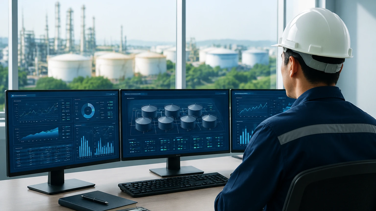
In a B2B context, the sensor is part of a larger ecosystem. A robust tank monitor system must communicate effectively with existing infrastructure.
* Analog Signals (4-20mA/HART): The industry standard for point-to-point communication. HART (Highway Addressable Remote Transducer) allows for digital configuration and diagnostics to be superimposed on the analog loop.
* Digital Protocols (Modbus/Profibus): Used for multi-drop installations where multiple tanks are monitored over a single cable, reducing wiring costs.
* Wireless and IoT: For remote tank farms or mobile storage, cellular or LoRaWAN-based tank monitor systems allow for cloud-based inventory tracking without the need for extensive cabling.
For comprehensive technical support and to review specific product options, engineers can visit the Main Page of Welk's industrial measurement division. Integrating these sensors into a centralized PLC (Programmable Logic Controller) or SCADA system allows for automated pump control, overfill alarms, and automated reordering of raw materials.
Limitations and Troubleshooting Common Issues
While modern systems are highly advanced, certain conditions remain challenging for level measurement:
1. Heavy Foam: Foam can absorb ultrasonic and radar signals, leading to signal loss. In these cases, a stilling well or a specialized low-frequency radar may be required.
2. Dust and Condensation: While radar penetrates dust effectively, heavy condensation on an ultrasonic transducer face can block the sound pulse. Self-cleaning or heated sensor faces are available for these environments.
3. Vapor Space Changes: In pressurized tanks, the gas composition can change the dielectric constant (for radar) or the speed of sound (for ultrasonic). High-frequency radar is generally the most resistant to these changes.
Frequently Asked Questions (FAQ)
Q: How do I choose between a contact and a non-contact tank monitor system?
A: Non-contact systems (Radar, Ultrasonic) are preferred for corrosive, abrasive, or hygienic applications where sensor wear or contamination must be avoided. Contact systems (Hydrostatic, Magnetic) are often chosen for their simplicity in specific pressurized or underground applications.
Q: Can a tank monitor system handle solids like powders or grains?
A: Yes, but it requires specific considerations. Radar (especially 80GHz) is excellent for solids because it can handle the low dielectric constant of many powders and the angled surface (angle of repose) of the material pile.
Q: What is the maintenance requirement for these systems?
A: Non-contact sensors are virtually maintenance-free as they have no moving parts. However, periodic verification of calibration and cleaning of the sensor face (if build-up occurs) is recommended annually. Hydrostatic sensors may require periodic zero-point checks.
Q: Is it possible to monitor tanks in remote locations without power?
A: Yes, battery-powered tank monitor systems with integrated wireless modules (NB-IoT or LoRaWAN) are designed specifically for remote monitoring, often providing several years of battery life with daily updates.
By carefully aligning the measurement technology with the physical realities of the application, organizations can ensure that their tank monitor system provides the reliable, accurate data necessary for modern industrial operations. For further guidance on selecting the right instrument for your specific process, consult the technical resources available on the Main Page.