Tank Monitoring Systems
Tank Monitoring Systems
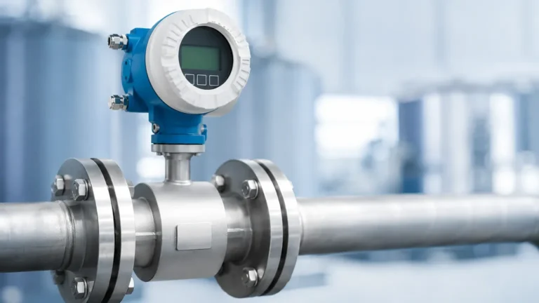
In the landscape of industrial automation, tank monitoring systems serve as the critical infrastructure for managing liquid inventory, ensuring process safety, and optimizing supply chain logistics. These systems are no longer merely about reading a local gauge; they represent an integrated framework of sensors, transmitters, and data processing units that provide real-time visibility into storage assets. Whether managing volatile chemicals, water treatment facilities, or oil and gas reserves, selecting the right monitoring technology is fundamental to operational efficiency.
Modern tank monitoring systems utilize various level measurement technologies to convert physical liquid heights into digital data. This data allows operators to prevent overfills, manage reorder points, and detect leaks before they escalate into environmental or safety hazards. Understanding the underlying measurement principles is the first step in designing a reliable monitoring solution.
Principles of Level Measurement in Monitoring Systems
To build an effective monitoring system, one must first understand how the primary sensors interact with the medium. Each technology has specific physical principles that dictate its suitability for different industrial environments.
Radar Level Measurement (Non-Contact and Guided)
Radar technology is widely considered the gold standard for high-accuracy tank monitoring. It operates on the Time of Flight (ToF) principle. The sensor emits electromagnetic pulses that travel at the speed of light. When these pulses hit the surface of the liquid, they are reflected back to the sensor. The system calculates the distance based on the time interval between emission and reception.
* 80GHz High-Frequency Radar: These sensors offer a narrow beam angle, which is ideal for tanks with internal obstructions like agitators or heating coils. They provide high precision, often within ±2mm.
* Guided Wave Radar (GWR): This technology uses a physical probe (cable or rod) to guide the microwave pulse. It is particularly effective in low dielectric constant liquids or applications with heavy foam and steam, as the probe ensures the signal reaches the liquid surface without dissipation.
Ultrasonic Level Measurement
Ultrasonic sensors function similarly to radar but use sound waves instead of electromagnetic waves. The transmitter emits an ultrasonic pulse (typically in the 20 kHz to 200 kHz range), which reflects off the liquid surface.
While cost-effective and easy to install, ultrasonic systems are sensitive to the medium's environment. Because sound requires a medium (air) to travel, changes in air temperature, pressure, or the presence of heavy vapors and foam can alter the speed of sound, leading to measurement errors. They are most commonly used in water treatment and open-channel flow applications where conditions are relatively stable.
Hydrostatic Pressure Measurement
Hydrostatic level transmitters measure the pressure exerted by the liquid column at the bottom of the tank. The principle is based on the formula: $P = \rho gh$ (where $P$ is pressure, $\rho$ is liquid density, $g$ is gravity, and $h$ is the height of the liquid).
These sensors are either mounted to the side of the tank via a flange or submerged directly into the liquid. Hydrostatic monitoring is highly reliable for vented tanks but requires compensation if the tank is pressurized, as the sensor must distinguish between liquid pressure and headspace pressure.
Magnetic Level Gauges and Switches
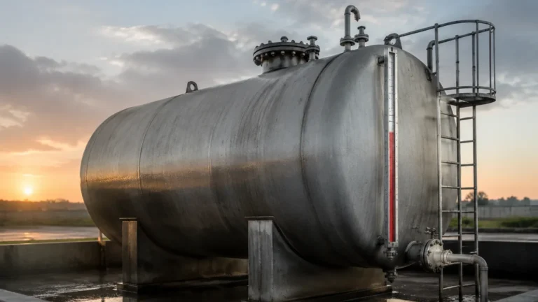
For high-visibility local monitoring combined with remote signaling, magnetic level gauges utilize a float containing a permanent magnet. As the liquid level changes, the float moves, flipping magnetic flags on an external scale and triggering reed switches or a magnetostrictive transmitter for remote data transmission. This is a robust solution for high-pressure and high-temperature bypass applications.
Key Components of Industrial Tank Monitoring Systems
A comprehensive system involves more than just a sensor. To provide actionable insights, the following components must work in unison:
1. Field Instrumentation: The primary sensors (radar, ultrasonic, or hydrostatic) that capture the raw level data.
2. Signal Transmission: Standardized outputs such as 4-20mA HART, RS485 Modbus, or wireless protocols (LoRaWAN, NB-IoT) that carry the signal from the tank to the control room.
3. Data Loggers and Gateways: These devices aggregate data from multiple tanks, often providing local display and buffering data in case of network outages.
4. Monitoring Software/Cloud Platforms: The interface where operators view levels, historical trends, and receive automated alerts. This is the core of modern tank monitoring systems, enabling remote access from any location.
For a detailed look at specific instrument specifications and how they integrate into these systems, you can Review product options and application support on the Welk Main Page.
Practical Selection Table for Tank Monitoring
Choosing the right technology depends on the physical properties of the liquid and the vessel's environment. The following table provides a general guide for technology selection:
| Technology | Typical Accuracy | Max Range | Media Suitability | Limitations |
| :— | :— | :— | :— | :— |
| 80GHz Radar | ±2 mm | 120 m (393 ft) | Chemicals, oils, solids | High initial cost |
| Guided Wave Radar | ±3 mm | 30 m (98 ft) | Low dielectric liquids, foam | Probe can be coated or corroded |
| Ultrasonic | ±0.25% of range | 15 m (49 ft) | Water, wastewater, acids | Affected by foam, vapor, and wind |
| Hydrostatic | ±0.1% to 0.5% | 200 m (656 ft) | Water, oils, fuel | Sensitive to density changes |
| Magnetic Gauge | ±5 mm | 6 m (20 ft) | High pressure/temp liquids | Limited to clean, non-coating liquids |
Installation Considerations and Best Practices
Even the most advanced sensor will fail if installed incorrectly. Engineering teams must adhere to several critical guidelines during the deployment of tank monitoring systems:
Dead Band (Blanking Distance)
Every non-contact sensor (radar and ultrasonic) has a "dead band" directly beneath the sensor face where it cannot measure accurately. If the liquid level enters this zone, the sensor may report a full tank or an error. Ensure the sensor is mounted high enough above the maximum fill line to account for this distance, which typically ranges from 100mm to 500mm depending on the model.
Nozzle Geometry and Positioning
For radar and ultrasonic sensors, the mounting nozzle should be as short as possible. If the nozzle is too long or narrow, it can cause internal reflections (ringing) that interfere with the surface signal. Furthermore, sensors should never be mounted in the center of a tank with a domed roof, as this can concentrate false echoes. The ideal position is usually 1/3 of the radius from the tank wall.
Obstruction Avoidance
Internal structures such as ladders, pipes, and agitators are common sources of false echoes. While modern software can "map out" these obstructions, it is best practice to install the sensor in a location with a clear line of sight to the liquid surface. For tanks with heavy agitation, using a stilling well or a guided wave radar is recommended to stabilize the surface signal.
Common Risks and Limitations
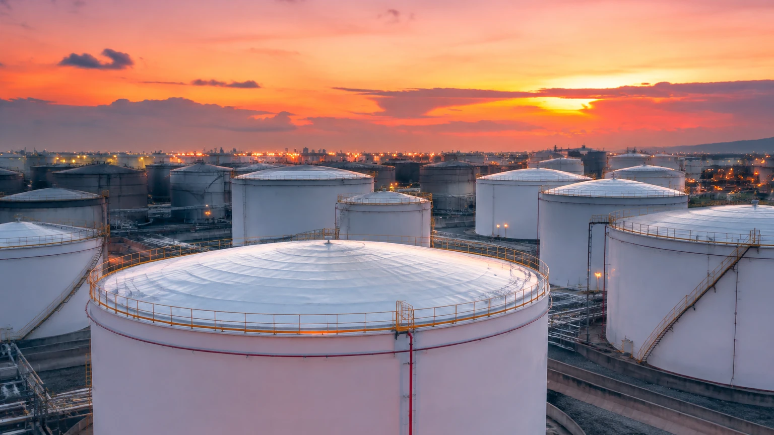
While technology has advanced, certain environmental factors still pose risks to the accuracy of tank monitoring systems:
* Vapor and Condensation: In chemical storage, heavy vapors can attenuate radar signals, while condensation on an ultrasonic transducer face can cause a "loss of echo." Many high-end radar sensors now feature PTFE lenses to shed condensation.
* Foam Absorption: Foam is a significant challenge for ultrasonic and non-contact radar. It acts as an acoustic or electromagnetic sponge, absorbing the signal. In these cases, hydrostatic or guided wave radar sensors are the preferred alternatives.
* Temperature Extremes: High temperatures can cause expansion of the tank shell and changes in the medium's density. Hydrostatic sensors must be temperature-compensated to maintain accuracy in outdoor tanks subject to seasonal shifts.
* Build-up and Scaling: In wastewater or mining slurries, material can build up on the sensor. Non-contact radar is generally more resistant to this than contact-based methods, but periodic maintenance and cleaning are still required.
Frequently Asked Questions (FAQ)
Q: How often do tank monitoring sensors need calibration?
A: This depends on the technology and the industry. Radar sensors are highly stable and may only need verification every 1-2 years. Hydrostatic sensors in critical chemical applications may require annual calibration due to potential drift in the pressure diaphragm.
Q: Can I monitor multiple tanks with a single system?
A: Yes. Modern digital gateways can aggregate signals from dozens of sensors via Modbus or wireless networks, presenting all data on a single dashboard.
Q: Is wireless monitoring secure for industrial use?
A: Industrial wireless protocols like WirelessHART or encrypted LoRaWAN are designed with robust security layers, including AES-128 encryption, making them suitable for most industrial monitoring needs.
Q: What is the difference between a level switch and a level transmitter?
A: A level switch provides point-level detection (e.g., "tank is 90% full") and is used for alarms or pump control. A level transmitter provides continuous monitoring (e.g., "tank is at 45.2%") and is the primary component of a tank monitoring system.
Conclusion and Project Confirmation
Implementing a successful tank monitoring strategy requires a thorough evaluation of the process environment and the physical properties of the liquid being measured. Before selecting a system, project managers and engineers should confirm the following:
* Medium Characteristics: Is the liquid corrosive, viscous, or prone to foaming? What is its dielectric constant (for radar) or density (for hydrostatic)?
* Tank Geometry: What are the height, diameter, and internal obstructions? Is the tank pressurized or vented?
* Integration Requirements: Does the data need to feed into an existing PLC/SCADA system, or is a standalone cloud-based platform required?
* Environmental Conditions: What are the ambient and process temperature ranges? Is the installation area classified as hazardous (Ex-rated)?
By addressing these factors and utilizing the appropriate measurement principles, organizations can deploy tank monitoring systems that provide long-term reliability and a clear return on investment.