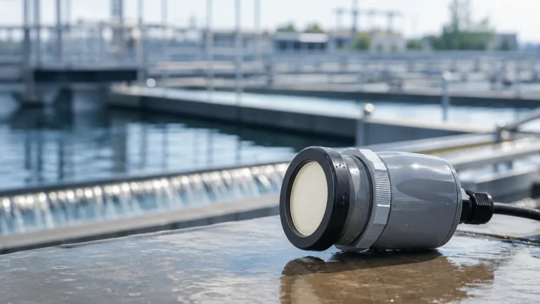
Tdl Analyzer
Tdl Analyzer
In the landscape of modern industrial process control, the TDL analyzer (Tunable Diode Laser analyzer) has emerged as a gold standard for gas concentration measurement. Utilizing the principles of absorption spectroscopy, these instruments offer high selectivity, rapid response times, and the ability to operate in harsh environments where traditional extractive sampling systems often fail. For engineers managing complex facilities—ranging from chemical plants to water treatment works—understanding the integration of gas analysis with broader instrumentation, such as those found on the Main Page, is essential for comprehensive process automation.
This guide provides a technical deep dive into TDL technology, selection criteria, and practical installation strategies for industrial applications.
Measurement Principles of TDL Analyzers
The core of a TDL analyzer is Tunable Diode Laser Spectroscopy (TDLS). This technique relies on the unique "spectral fingerprint" of gas molecules. Every gas species absorbs light at specific, narrow wavelengths. By using a laser diode that can be precisely tuned to these specific wavelengths, the analyzer can detect the presence and concentration of a target gas without interference from other components in the gas stream.
The Beer-Lambert Law
The fundamental physics governing a TDL analyzer is the Beer-Lambert Law, which describes the relationship between the absorption of light and the properties of the material through which the light is traveling. The formula is generally expressed as:
$$A = \epsilon \cdot c \cdot L$$
Where:
- A is the absorbance (the amount of light absorbed).
- \epsilon (Epsilon) is the molar absorption coefficient (a constant for a specific gas at a specific wavelength).
- c is the concentration of the gas.
- L is the optical path length (the distance the laser travels through the gas).
In a practical TDL analyzer, the instrument measures the intensity of the laser light before and after it passes through the process medium. Since the path length and absorption coefficient are known, the electronics can calculate the gas concentration in real-time.
Direct Absorption vs. Wavelength Modulation
There are two primary methods used in TDL analyzers to process this signal:
1. Direct Absorption Spectroscopy: The laser scans across the absorption peak, and the total loss of light is measured. This is straightforward but can be sensitive to noise in high-dust environments.
2. Wavelength Modulation Spectroscopy (WMS): The laser frequency is modulated at a high frequency while scanning the absorption line. This allows the detector to use phase-sensitive detection (lock-in amplification), significantly improving the signal-to-noise ratio. WMS is preferred for detecting very low concentrations (trace analysis) or working in processes with high particulate loads.
System Architecture and Components
A TDL analyzer is typically comprised of three main assemblies: the Transmitter (Launch) Unit, the Receiver Unit, and the Central Processing Unit (though in many modern "cross-stack" designs, the processing electronics are integrated into the transmitter or receiver).
* The Laser Source: Usually a Vertical-Cavity Surface-Emitting Laser (VCSEL) or a Distributed Feedback (DFB) laser. These are chosen for their narrow linewidth and stability.
* Optical Windows: These separate the sensitive electronics from the process gas. They must be made of materials transparent to the specific laser wavelength (e.g., quartz, sapphire, or calcium fluoride).
* The Detector: A photodiode (often InGaAs) that converts the remaining laser light into an electrical signal.
* Purge System: Because the windows are in contact with the process, a constant flow of clean, dry instrument air or Nitrogen (N2) is used to keep the optical surfaces free from condensation and dust.
Technical Selection Criteria
Choosing the correct TDL analyzer requires a detailed understanding of the process conditions. Unlike level meters, which focus on physical boundaries, a TDL analyzer must account for the chemical and thermal behavior of the gas phase.
Selection Table: Application Parameters
| Parameter | Requirement/Range | Impact on Selection |
| :— | :— | :— |
| Target Gas | O2, CO, CO2, H2O, NH3, CH4, HCl | Determines the required laser wavelength. |
| Path Length | 0.5 m to 20 m | Longer paths increase sensitivity but require better alignment. |
| Process Temperature | Up to 1500 °C | Requires specialized cooling and high-temperature window seals. |
| Process Pressure | 0.5 bar to 20 bar | Pressure causes "line broadening," requiring advanced software compensation. |
| Dust Load | < 1 g/m³ to > 50 g/m³ | High dust requires Wavelength Modulation Spectroscopy (WMS). |
| Response Time | Typically < 2 seconds | Critical for safety-related applications (e.g., O2 monitoring). |
Cross-Interference and Selectivity
One of the primary advantages of a TDL analyzer is its high selectivity. Because the laser linewidth is much narrower than the absorption lines of the gas, the instrument can distinguish between molecules that would otherwise overlap in traditional Non-Dispersive Infrared (NDIR) sensors. For example, measuring moisture (H2O) in the presence of high CO2 concentrations is a common challenge that TDL solves effectively.
Installation and Engineering Considerations
Proper installation is the most critical factor in the long-term reliability of a TDL analyzer. Because the measurement relies on a beam of light crossing a duct or pipe, mechanical stability is paramount.
Mechanical Alignment
In cross-stack installations, the transmitter and receiver are mounted on opposite sides of the process vessel. Any shifting of the vessel walls due to thermal expansion or vibration can cause the laser beam to miss the detector.
- Standoff Pipes: Use rigid, heavy-walled pipes for mounting flanges.
- Alignment Hubs: Most TDL analyzers include adjustable bellows or X-Y adjustment plates to fine-tune the beam path after installation.
Purging Requirements
Purging is not optional for most in-situ TDL analyzers. The purge gas serves two roles: it keeps the windows clean and it cools the optical components.
- Flow Rate: Typically 10 to 50 L/min per side.
- Gas Quality: Must be free of the target gas. For example, if you are measuring O2, you cannot use instrument air as a purge gas; you must use Nitrogen.
- Check Valves: Always install check valves in the purge lines to prevent process gas from backing up into the air supply if the purge pressure fails.
Thermal Insulation
If the process gas is hot and contains moisture, the area around the mounting flanges must be insulated. If the temperature drops below the dew point near the windows, condensation will occur, blocking the laser beam and triggering a "low transmission" alarm.

Limitations and Operational Risks
While highly robust, TDL analyzers are not universal solutions. Engineers should be aware of the following limitations:
1. Particulate Blocking: If the dust load is extremely high (e.g., in a cement kiln pre-heater), the laser light may be completely extinguished. While WMS can handle up to 90% light loss, 100% loss results in a signal failure.
2. Pressure and Temperature Shifts: TDL measurements are density-dependent. If the process pressure or temperature fluctuates significantly, the analyzer must receive real-time inputs from external sensors to compensate for these changes.
3. Path Length Constraints: In very small pipes (less than 0.5 meters), the optical path may be too short to achieve the desired detection limit. In these cases, an extractive TDL system or a folded-path probe is required.
4. Spectral Availability: Not all gases have usable absorption lines in the near-infrared or mid-infrared regions where diode lasers operate reliably. For example, noble gases (Argon, Helium) cannot be measured with TDL.
Integration with Process Instrumentation
In modern industrial environments, a TDL analyzer rarely operates in isolation. It is typically part of a larger control loop that includes level measurement, pressure sensing, and flow control. For instance, in a chemical storage tank, a TDL analyzer may monitor the Oxygen concentration in the vapor space (blanketing) to prevent explosion hazards, while a radar level meter monitors the liquid volume.
Reliable instrumentation from providers like those listed on the Main Page ensures that both the gas phase and liquid phase are monitored with the same level of precision, allowing for a unified safety and production strategy.
Frequently Asked Questions (FAQs)
Q: How often does a TDL analyzer need to be calibrated?
A: TDL analyzers are known for their high stability. Unlike electrochemical sensors that drift as they consume electrolyte, the laser frequency is locked. Most units only require a validation check once every 6 to 12 months using a flow-through calibration cell. Internal reference cells in many units provide continuous "line locking" to prevent spectral drift.
Q: Can a TDL analyzer measure multiple gases at once?
A: Yes, some advanced TDL analyzers use multiple laser diodes or a single laser that can scan across absorption lines of two different species (e.g., CO and H2O). However, this increases the complexity and cost of the instrument.
Q: What happens if the laser diode fails?
A: Laser diodes have a typical lifespan of 5 to 10 years. Most TDL analyzers include diagnostic software that monitors the laser's health (e.g., threshold current). If the laser fails, the unit will output a fault signal via 4-20mA or digital bus (HART, Modbus, or Foundation Fieldbus).
Q: Is a TDL analyzer suitable for SIL-rated safety loops?
A: Yes, many TDL analyzers are certified for use in SIL 2 or SIL 3 environments, particularly for O2 monitoring in flare headers or inerting systems, due to their rapid response time and self-diagnostic capabilities.
Conclusion
The TDL analyzer represents a significant leap forward in gas analysis technology, offering a non-contact, low-maintenance solution for the most demanding industrial processes. By understanding the physics of absorption and adhering to strict installation guidelines regarding alignment and purging, engineers can achieve unprecedented accuracy in gas concentration monitoring. When combined with high-quality level and pressure instrumentation, these analyzers form the backbone of a safe and efficient industrial operation.