Thermal Flow Meter
Thermal Flow Meter
Thermal flow meters, often referred to as thermal mass flow meters, represent a critical technology in the field of industrial gas measurement. Unlike traditional volumetric flow meters that require additional sensors for pressure and temperature compensation, thermal flow meters provide a direct measurement of mass flow. This capability is particularly valuable in industrial automation, where precise gas monitoring is essential for process efficiency, safety, and cost control. As a specialized manufacturer, Welk provides these instruments to meet the rigorous demands of sectors ranging from water treatment to chemical processing.
Fundamental Principles of Thermal Mass Flow Measurement
The operation of a thermal flow meter is based on the physical principle of heat transfer. Specifically, it utilizes the fact that a fluid (usually a gas) flowing past a heated surface will carry away heat at a rate proportional to its mass flow. This relationship is often described by King’s Law.
Most modern thermal flow meters utilize two Resistance Temperature Detectors (RTDs) as sensors. One RTD acts as a reference sensor, measuring the ambient temperature of the gas. The second RTD is the active or heated sensor. There are two primary methods used to process the signal from these sensors:
1. Constant Temperature Differential: In this method, the electronics provide a variable amount of power to the heated sensor to maintain a constant temperature difference (delta T) between it and the reference sensor. As the gas flow increases, more cooling occurs, and more power is required to maintain the differential. This power consumption is directly proportional to the mass flow rate.
2. Constant Power: Here, a fixed amount of power is supplied to the heated sensor. The temperature difference between the two sensors is measured. At higher flow rates, the cooling effect is greater, resulting in a smaller temperature difference. This method is often used in simpler applications but can be less responsive at very high or very low flow rates compared to the constant temperature differential method.
Because the measurement is based on the heat capacity and thermal conductivity of the gas molecules, the meter effectively counts the number of molecules passing the sensor, regardless of the gas pressure or temperature, within the instrument's operating limits.
Key Advantages in Industrial Applications
Thermal flow meters are preferred in many B2B industrial environments due to several distinct technical advantages:
* Direct Mass Flow Measurement: No need for external pressure or temperature transmitters, reducing both hardware costs and potential points of failure.
* High Turndown Ratio: These meters can accurately measure extremely low flow velocities (as low as 0.1 m/s) and maintain accuracy up to high velocities (over 100 m/s). Turndown ratios of 100:1 or even 1000:1 are common.
* Low Pressure Drop: Insertion-style thermal flow meters present minimal obstruction to the flow, which is crucial for low-pressure gas lines or large ducting where energy loss must be minimized.
* No Moving Parts: The absence of mechanical components such as turbines or gears means there is no wear and tear, leading to high reliability and long-term stability in harsh industrial environments.
* Sensitivity: They are exceptionally sensitive to low flow rates, making them ideal for leak detection or monitoring pilot light gas consumption.
Selection Criteria and Evaluation
When selecting a thermal flow meter for a specific project, engineers must evaluate several factors to ensure the instrument matches the process conditions. Before reviewing specific models on the Welk Main Page, consider the following evaluation criteria:
Gas Composition
Thermal flow meters are calibrated for specific gases or gas mixtures. Since the measurement relies on the thermal properties of the gas (specific heat and thermal conductivity), a change in gas composition will result in measurement errors. For example, a meter calibrated for pure Nitrogen (N2) will not read correctly if used for Carbon Dioxide (CO2) without recalibration or a correction factor.
Flow Profile and Pipe Size
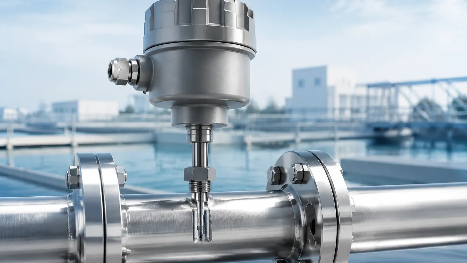
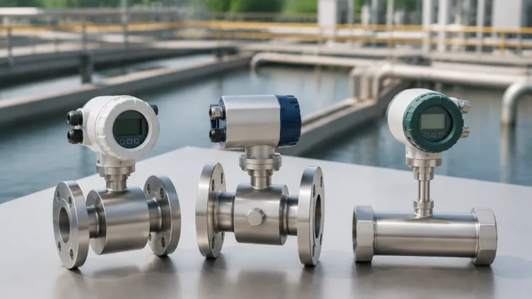
For pipe diameters smaller than 50 mm (2 inches), an inline thermal flow meter is typically recommended. These include a built-in flow body and often flow conditioners to ensure a stable profile. For larger pipes or ducts, insertion-style meters are more cost-effective and easier to install.
Process Temperature and Pressure
While thermal meters are excellent for mass flow, they have upper limits for temperature (typically up to 250°C or 450°C for specialized models) and pressure (standard models often handle up to 4 MPa or 40 bar). High-pressure applications require robust sensor designs to prevent mechanical deformation.
Technical Selection Table
The following table provides a general guideline for choosing between different thermal flow meter configurations based on common industrial applications.
| Application | Recommended Meter Type | Key Reason for Selection |
| :— | :— | :— |
| Compressed Air Monitoring | Insertion Thermal Meter | Easy installation in existing lines; low pressure drop. |
| Natural Gas Billing | Inline Thermal Meter | High accuracy and stability; factory-calibrated flow body. |
| Wastewater Aeration | Insertion Thermal Meter | Measures low-pressure air in large diameter pipes (300mm+). |
| Flare Gas Measurement | Insertion (Heavy Duty) | Handles wide turndown ratios and varying flow velocities. |
| Lab-scale Gas Mixing | Inline (Miniature) | Precise control of small mass flow rates. |
| HVAC Duct Flow | Insertion (Light Duty) | Cost-effective for large-scale air handling systems. |
Installation Guidelines for Optimal Accuracy
Proper installation is paramount for the accuracy of any thermal flow meter. Because the sensor measures flow at a specific point (for insertion types) or within a small cross-section, a fully developed, non-turbulent flow profile is required.
1. Straight Pipe Runs: Standard installations typically require a minimum of 20 diameters (20D) of straight pipe upstream of the sensor and 5 to 10 diameters (5D-10D) downstream. If obstructions like elbows, valves, or reducers are present, these requirements may increase.
2. Insertion Depth: For insertion meters, the sensor must be placed at the point of average velocity, which is usually the center of the pipe for turbulent flow. Incorrect depth is a leading cause of measurement error.
3. Orientation: In gas lines where moisture might condense, the meter should be installed on the side or top of the pipe (between the 10 o'clock and 2 o'clock positions) to prevent water droplets from hitting the heated sensor and causing "spikes" in the reading.
4. Flow Conditioning: If the required straight runs are unavailable, flow conditioners (vane-type or perforated plates) can be used to artificially create a stable flow profile in a shorter distance.
Limitations and Operational Risks
While highly versatile, thermal flow meters are not suitable for every application. Understanding these limitations prevents costly misapplications:
* Moisture and Droplets: Thermal flow meters are designed for dry gases. If liquid droplets hit the heated sensor, the meter will interpret the rapid cooling as a massive surge in gas flow. In saturated gas applications, specialized designs or heated sensors are necessary to mitigate this.
* Sensor Coating: In applications like untreated wastewater gas or heavy industrial exhaust, particulates or oils can coat the sensor. This coating acts as an insulator, slowing down the heat transfer and causing the meter to under-read. Regular cleaning or the use of self-cleaning sensor designs may be required.
* Changing Gas Mixtures: As mentioned, these meters are gas-specific. They are not suitable for processes where the gas composition changes frequently and unpredictably (e.g., some chemical reactor off-gases).
* High Velocity Limits: While they have great low-end sensitivity, at extremely high velocities, the cooling effect plateaus, and the meter may lose accuracy or reach its electronic limit.
Frequently Asked Questions (FAQ)
Q: Do I need to recalibrate my thermal flow meter if my line pressure changes?
A: No. One of the primary benefits of a thermal mass flow meter is that it is inherently compensated for pressure changes. As long as the pressure remains within the mechanical design limits of the sensor, the mass flow reading remains accurate.
Q: Can a thermal flow meter be used for liquids?
A: While the principle of thermal dispersion works in liquids, thermal mass flow meters are almost exclusively used for gases in industrial settings. Liquid flow measurement usually employs electromagnetic, ultrasonic, or Coriolis technologies due to the different thermal properties of fluids.
Q: How does a thermal flow meter compare to a Vortex meter?
A: Vortex meters are excellent for high-velocity steam and gas and are less sensitive to gas composition. However, thermal flow meters are far superior for low-flow applications and do not require separate pressure/temperature sensors for mass flow calculation.
Q: What maintenance is required?
A: If the gas is clean and dry, maintenance is minimal. For dirty gas applications, the sensor should be inspected periodically for buildup. Many Welk instruments feature robust sensor designs that allow for easy removal and cleaning without decommissioning the entire pipe run.
Conclusion
The thermal flow meter is a powerhouse of gas measurement, offering unparalleled sensitivity and the convenience of direct mass flow data. Whether monitoring compressed air efficiency or managing biogas production, selecting the right configuration—inline or insertion—and ensuring proper installation are the keys to long-term success. For technical specifications, CAD drawings, and application-specific advice, engineers and procurement professionals should consult the comprehensive resources available on the Main Page of the Welk website. By matching the instrument to the specific thermal properties of the process gas, industrial facilities can achieve higher levels of precision and operational control.