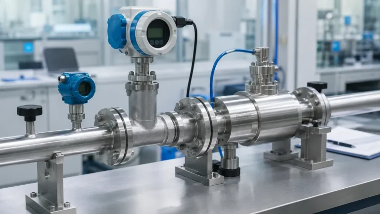
Thermal Mass Flow
Thermal Mass Flow
In the landscape of industrial process control, the accurate measurement of gas and liquid movement is fundamental to efficiency, safety, and cost management. Thermal mass flow measurement has emerged as a preferred technology for many applications due to its ability to measure the mass flow of fluids directly, without the need for additional pressure or temperature compensation. While often discussed in the context of flow meters, the underlying principle of thermal dispersion is also a critical component in advanced level sensing technology, particularly in point-level detection for challenging industrial environments.
Understanding the Principle of Thermal Mass Flow Measurement
Thermal mass flow technology operates on the physical principle of heat transfer. Specifically, it utilizes the cooling effect of a moving fluid as it passes over a heated surface. In a typical industrial sensor, two RTD (Resistance Temperature Detector) sensors are placed in the flow stream. One sensor serves as the reference, measuring the ambient temperature of the fluid. The second sensor is heated to a specific, constant temperature differential above the reference sensor.
As the fluid (gas or liquid) moves past the heated sensor, it carries away heat—a process known as thermal dispersion. The amount of heat lost is directly proportional to the mass flow rate of the fluid. In a "constant temperature" circuit, the instrument measures the amount of electrical power required to maintain the fixed temperature difference. In a "constant power" circuit, the instrument measures the temperature difference itself, which decreases as flow increases.
This relationship is governed by King’s Law, which describes how the heat loss from a cylinder in a flowing fluid is related to the mass velocity of that fluid. Because the heat transfer depends on the molecular density of the fluid (its specific heat and thermal conductivity), the measurement is inherently a mass flow reading. This distinguishes it from volumetric technologies, such as vortex or turbine meters, which measure the space the fluid occupies regardless of its density.
Direct Mass Measurement vs. Volumetric Measurement
For industrial operators, the distinction between mass and volume is critical. Gases are highly compressible; their volume changes significantly with variations in pressure and temperature. A volumetric flow of 100 cubic meters per hour at 1 bar (100 kPa) contains far fewer gas molecules than 100 cubic meters per hour at 10 bar (1,000 kPa).
To obtain an accurate mass reading with volumetric meters, engineers must install separate pressure and temperature transmitters and use a flow computer to calculate the compensated flow. Thermal mass flow instruments eliminate this complexity. By measuring the cooling effect on a molecular level, they provide a standardized mass flow output (such as kg/h or Standard Liters Per Minute) regardless of process fluctuations. This makes them ideal for applications like compressed air auditing, natural gas monitoring, and aeration control in water treatment plants.
Thermal Dispersion in Level Sensing Applications
While thermal mass flow is primarily associated with moving fluids in pipes, the same physics apply to level measurement. Thermal dispersion level switches are used to detect the presence or absence of a medium at a specific point in a tank or vessel.
In this application, the sensor detects the change in heat dissipation between the gas phase (usually air or vapor) and the liquid phase. Since liquids typically have much higher thermal conductivity and heat capacity than gases, the sensor cools down much faster when submerged in liquid. This sharp change in the power required to maintain the temperature differential triggers the switch.
These devices are particularly useful for detecting interface levels between two different liquids or for high-level alarms in viscous or foaming fluids where traditional float switches or ultrasonic sensors might fail. As a professional manufacturer of industrial level measurement instruments, Welk provides a range of solutions that leverage various physical principles, including radar and ultrasonic, to ensure reliable monitoring. For more information on the full suite of measurement technologies, you can visit the Main Page.
Critical Selection Criteria for Industrial Applications
Selecting the right thermal mass flow instrument requires a detailed understanding of the process conditions. Because the measurement relies on the specific thermal properties of the fluid, the instrument must be calibrated for the specific gas or liquid mixture it will encounter.
1. Gas Composition and Calibration
Thermal mass flow meters are highly sensitive to changes in gas composition. If a meter is calibrated for pure Nitrogen but used for Carbon Dioxide, the readings will be significantly inaccurate because the specific heat ($C_p$) and thermal conductivity of the two gases differ. For applications involving mixed gases, such as flare gas or biogas, the exact percentages of each component must be known to provide an accurate calibration curve.
2. Flow Range and Turndown Ratio
One of the greatest advantages of thermal technology is its high turndown ratio, often exceeding 100:1. This allows the sensor to detect very low flow velocities (leakage) as well as high-velocity process flows. This is superior to differential pressure (DP) flow meters, which typically struggle at the lower 20% of their range.
3. Pipe Size and Mounting Style
Instruments are generally available in two configurations:
* In-line (Spool piece): Used for smaller pipes, typically below 50 mm (2 inches). These provide the highest accuracy because the flow profile is controlled within the factory-calibrated tube.
* Insertion: Used for larger pipes and ducts. The probe is inserted through a flange or compression fitting. While more cost-effective for large diameters, they require careful placement to account for the flow profile across the pipe.
Selection Table: Comparison of Sensor Configurations
| Feature | In-line Thermal Meter | Insertion Thermal Meter | Thermal Level Switch |
| :— | :— | :— | :— |
| Primary Use | High-accuracy gas flow | Large duct/pipe gas flow | Point level detection |
| Typical Pipe Size | 6 mm to 50 mm | 50 mm to 2000 mm+ | N/A (Vessel mounted) |
| Accuracy | ±1% of Reading | ±1% to 3% of Full Scale | N/A (Binary output) |
| Pressure Drop | Low to Moderate | Negligible | N/A |
| Installation | Flanged or Threaded | Compression/Hot Tap | Threaded or Flanged |
Installation Guidelines and Best Practices
To achieve the specified accuracy of a thermal mass flow meter, the flow profile at the sensing point must be stable and fully developed (laminar). Turbulent flow caused by elbows, valves, or reducers will lead to erratic readings.
* Straight Pipe Runs: A general rule of thumb is to provide at least 20 diameters (20D) of straight pipe upstream of the sensor and 5 diameters (5D) downstream. If space is limited, flow conditioners (perforated plates) can be used to reduce the required straight run.
* Orientation: For gas applications, the sensor should ideally be mounted on the side or top of the pipe to prevent moisture or condensate from pooling on the sensor tips. For liquid applications, the pipe must always be full.
* Cleanliness: While thermal sensors have no moving parts, the buildup of oil, dust, or scale on the sensor probe acts as an insulator, slowing the heat transfer and causing the meter to under-read. Regular inspection and cleaning are necessary in "dirty" gas applications.
Limitations and Common Operational Risks
Despite its versatility, thermal mass flow technology is not a universal solution. Engineers should be aware of the following limitations:
* Moisture and Condensate: Thermal flow meters are highly sensitive to moisture droplets. If a water droplet hits the heated sensor, it absorbs a massive amount of energy as it evaporates, causing a momentary "spike" in the flow reading. In saturated gas streams, such as untreated compressed air or biogas, water knockout pots or heated sensors are required.
* Temperature Limits: Standard thermal sensors are typically limited to processes below 200°C (392°F). High-temperature versions exist but are specialized and more costly.
* Fluid Properties: This technology is primarily used for gases. While it can be used for liquids, the high power requirements and potential for "film boiling" on the sensor surface limit its use to specific low-flow liquid applications or level switching.
Frequently Asked Questions (FAQs)
Q: Does thermal mass flow require periodic recalibration?
A: Yes. While the electronics are stable, the physical condition of the sensor probe can change due to erosion or coating. For regulated industries or custody transfer, annual calibration is recommended. For general process monitoring, a field validation check of the sensor's resistance is often sufficient.
Q: Can I use one thermal mass flow meter for different gases?
A: Only if the meter supports multiple gas curves. Modern digital meters often come pre-programmed with a library of common gases (Air, Ar, CO2, N2, etc.). However, switching the gas type without updating the meter's internal compensation will result in significant errors.
Q: How does pressure affect the reading?
A: Theoretically, thermal mass flow is independent of pressure. However, at very high pressures (e.g., above 30 bar / 435 psi), the thermal properties of some gases change slightly. Most high-quality manufacturers include a pressure correction factor in their calibration for these conditions.
Conclusion
Thermal mass flow represents a robust and highly efficient method for managing gas resources in industrial environments. By providing direct mass measurement and exceptional sensitivity at low flow rates, it allows for precise control of aeration, combustion, and distribution systems. When applied as a level sensing technology, thermal dispersion offers a reliable, no-moving-parts alternative for challenging point-level applications.
Success with this technology depends on accurate gas characterization, adherence to installation straight-run requirements, and proactive management of moisture and contamination. For engineers looking to integrate these or other level and flow measurement solutions, reviewing technical specifications and application support on the Main Page is a recommended next step to ensure the selected instrument matches the specific demands of the process environment.