Thermodesk
Thermodesk
In the modern industrial landscape, the integration of ergonomic hardware and sophisticated data monitoring is essential for operational efficiency. The term "thermodesk" often refers to specialized workstations or control environments designed to manage thermal loads while providing engineers with a centralized hub for process monitoring. In the context of industrial automation and level measurement, a thermodesk setup serves as the primary interface between field instrumentation and the decision-making process. For professionals managing water treatment, chemical processing, or oil and gas facilities, understanding how level measurement data is captured, transmitted, and visualized at these stations is critical for maintaining system integrity.
Reliable level measurement starts at the tank or vessel. Instruments such as radar level meters, ultrasonic sensors, and hydrostatic transmitters provide the raw data that populates the screens of a thermodesk. By ensuring that the measurement principles are correctly matched to the application, operators can rely on the accuracy of the information displayed at their workstations.
Principles of Industrial Level Measurement
Before selecting the hardware that feeds into a control room or thermodesk, it is necessary to understand the underlying physics of the most common level measurement technologies. Each method has specific strengths and limitations based on the physical properties of the medium and the environmental conditions of the vessel.
Radar Level Measurement (ToF)
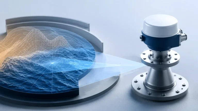
Radar level meters operate on the Time-of-Flight (ToF) principle. The sensor emits high-frequency microwave pulses (typically in the 26 GHz or 80 GHz range). These pulses reflect off the surface of the product and return to the antenna. The instrument calculates the distance based on the time elapsed between emission and reception. Radar is highly valued in B2B applications because it is non-contact and largely unaffected by changes in temperature, pressure, or vapor space composition.
Ultrasonic Level Sensing
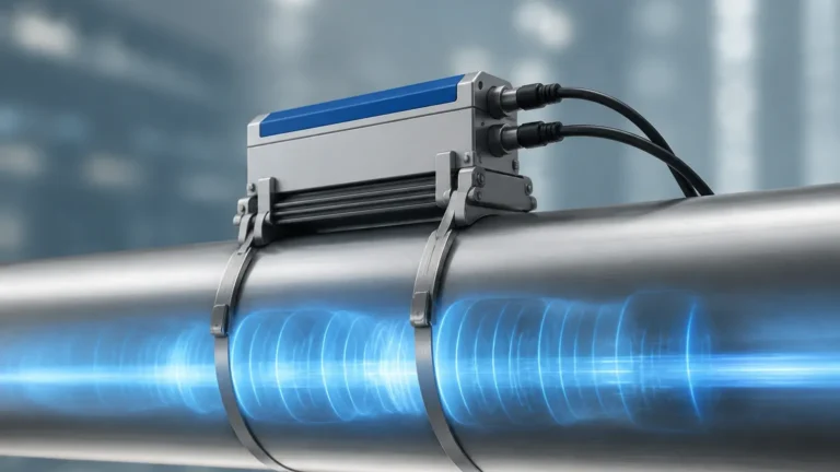
Similar to radar, ultrasonic sensors use the ToF principle but utilize sound waves instead of electromagnetic waves. A transducer emits an ultrasonic pulse that bounces off the liquid surface. Because the speed of sound is influenced by air temperature, these sensors usually include integrated temperature compensation. They are cost-effective for open-air applications like water basins but can struggle in vacuum conditions or where heavy foam is present.
Hydrostatic Level Transmission
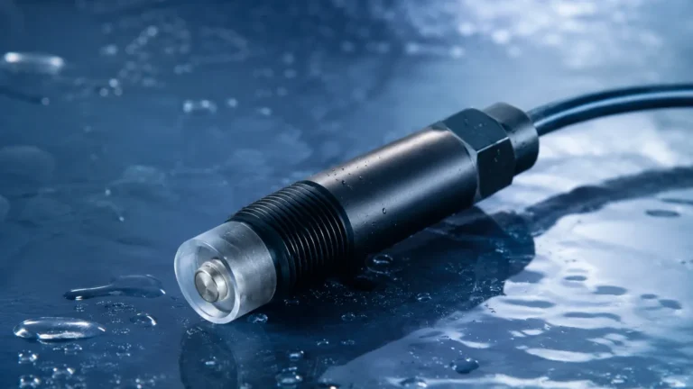
Hydrostatic sensors measure the pressure exerted by a liquid column. The pressure at the bottom of a tank is directly proportional to the height of the liquid and its density ($P = \rho \cdot g \cdot h$). This is a contact-based method where the transmitter is either submerged or mounted to a flange at the bottom of the vessel. It is a robust solution for vented tanks where density remains constant.
Magnetic Level Gauges
Magnetic level gauges utilize a float containing a permanent magnet. As the liquid level rises and falls, the float moves accordingly within a bypass chamber. This motion is coupled with an external indicator or a reed-chain transmitter. This provides both a local visual reading and a remote signal for the control station, making it a favorite for high-pressure and high-temperature boiler applications.
Integrating Field Data with the Thermodesk Environment
The effectiveness of a thermodesk as a monitoring hub depends on the quality of the signal integration. Most modern level meters from manufacturers like Welk offer various output protocols, including 4-20mA HART, Modbus RS485, and Foundation Fieldbus. When designing the control room interface, engineers must confirm that the power supply and signal conditioning at the workstation can handle the data density required for real-time process control.
For comprehensive technical specifications and to Review product options and application support, engineers should consult the Main Page of the primary equipment provider to ensure compatibility between field devices and control room hardware.
Technology Selection Table
Choosing the right instrument requires a comparison of process parameters. The following table provides a general guideline for selecting level measurement technologies based on common industrial requirements.
| Technology | Medium Type | Maximum Range | Accuracy | Typical Applications |
| :— | :— | :— | :— | :— |
| 80GHz Radar | Liquids/Solids | 120m | ±1mm | Chemical tanks, silos, corrosive media |
| Ultrasonic | Liquids | 15m – 30m | ±0.25% | Water treatment, open channels |
| Hydrostatic | Liquids | 200m (H2O) | ±0.1% | Deep wells, vented fuel tanks |
| Magnetic Gauge| Liquids | 6m+ | ±5mm | Boilers, oil-water separators |
| Level Switch | Liquids/Solids | N/A (Point) | ±1mm | Overfill protection, pump control |
Installation and Engineering Considerations
To ensure that the data reaching the thermodesk is accurate, specific installation protocols must be followed. Errors in the field cannot be corrected by software at the workstation.
1. Blocking Distance (Dead Band): Every non-contact sensor (Radar and Ultrasonic) has a minimum distance near the antenna where measurements cannot be taken. For ultrasonic sensors, this is typically 0.25m to 0.6m. Ensure the maximum expected liquid level does not enter this zone.
2. Internal Obstructions: Agitators, ladders, and heating coils can create false echoes. While modern radar meters feature "false echo suppression," it is best practice to install the sensor in a location with a clear line of sight to the product surface.
3. Beam Angle: The signal from a radar or ultrasonic sensor spreads in a cone shape. The higher the frequency (e.g., 80GHz), the narrower the beam. A narrow beam is essential for narrow tanks or vessels with complex internal structures.
4. Stilling Wells: In applications with heavy turbulence or surface foam, installing a radar or float-based sensor inside a stilling well (a perforated pipe) can stabilize the reading.

Limitations and Common Risks
While industrial level measurement technology has advanced significantly, certain risks remain that can compromise the data integrity at the thermodesk.
* Dielectric Constant (Dk): Radar relies on the reflectivity of the medium. Materials with a very low dielectric constant (like certain oils or liquefied gases) reflect less energy. In these cases, guided wave radar (GWR) or high-sensitivity 80GHz radar is required.
* Vapor and Condensation: Heavy steam or condensation on an ultrasonic transducer face can block the sound pulse entirely. Radar is generally immune to vapor but may require an air purge or a specialized lens antenna if heavy buildup is expected.
* Density Variations: Hydrostatic transmitters are sensitive to changes in fluid density. If the temperature of the liquid fluctuates significantly, the density will change, leading to a calculated level error unless a temperature-compensated system is used.
Confirmation Steps for Project Engineers
Before finalizing the procurement of level instrumentation for a project involving a thermodesk or centralized control system, the following factors should be confirmed:
* Process Temperature and Pressure: Ensure the sensor housing and wetted materials (316L SS, PTFE, etc.) are rated for the maximum possible process excursions.
* Output Requirements: Confirm if the system requires a simple analog signal or a digital protocol that provides secondary variables like sensor temperature or signal strength.
* Hazardous Area Ratings: If the vessel is in a volatile environment, verify that the instruments carry the necessary ATEX, IECEx, or UL certifications for intrinsic safety or explosion-proof operation.
* Mounting Connections: Double-check flange sizes (DN or ANSI) or thread types (G or NPT) to avoid installation delays.
Frequently Asked Questions (FAQ)
Q: How does a thermodesk environment benefit from 80GHz radar technology?
A: 80GHz radar provides a much higher signal-to-noise ratio and a narrower beam angle. This results in cleaner data with fewer false echoes, reducing the need for complex signal processing at the control desk and providing more reliable real-time monitoring.
Q: Can ultrasonic sensors be used for solids measurement?
A: While possible for some powders, ultrasonic waves are often absorbed by uneven solid surfaces. Radar is generally preferred for solids due to its better penetration and reflection characteristics.
Q: What maintenance is required for these sensors?
A: Non-contact sensors like radar and ultrasonic units are virtually maintenance-free as they have no moving parts. However, periodic inspection for material buildup on the antenna or transducer face is recommended in dusty or sticky applications.
Q: Is it possible to integrate legacy magnetic gauges into a digital thermodesk?
A: Yes, by adding a reed-chain transmitter or a magnetostrictive sensor to the outside of the magnetic gauge chamber, the local visual reading can be converted into a 4-20mA or digital signal for remote monitoring.
By carefully selecting the appropriate level measurement technology and ensuring precise installation, industrial operators can maximize the utility of their thermodesk workstations, leading to safer and more efficient process management. For further technical guidance and product specifications, visiting the Main Page of a specialized manufacturer is the recommended next step for engineering teams.