Time Constant
Time Constant
In the field of industrial process control and level measurement, the term "time constant" refers to a fundamental parameter that dictates how quickly a measurement instrument responds to changes in the process variable. For engineers and technicians designing automation systems, understanding the time constant is essential for balancing signal stability with responsiveness. Whether monitoring a high-speed filling line or a massive crude oil storage tank, the configuration of the time constant—often referred to as damping or integration time—directly impacts the accuracy of the data fed into Programmable Logic Controllers (PLCs) and Distributed Control Systems (DCS).
As a professional manufacturer of industrial level measurement instruments, Welk provides a range of sensors, including radar, ultrasonic, and hydrostatic transmitters, all of which utilize adjustable time constants to optimize performance in diverse environments. This guide explores the technical principles of the time constant, its application across different measurement technologies, and practical selection criteria for industrial projects.
Measurement Principles of the Time Constant
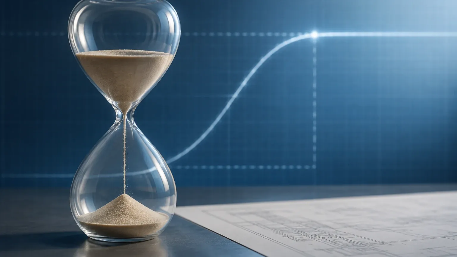
The time constant (typically denoted by the Greek letter tau, $\tau$) is a characteristic of a first-order linear time-invariant system. In the context of a level transmitter, it represents the time required for the instrument's output signal to reach approximately 63.2% of its final value following a step change in the actual liquid level.
The 63.2% Rule
When a level change occurs abruptly—for example, a sudden discharge from a tank—the sensor does not immediately jump to the new value. Instead, the output follows an exponential curve. After one time constant ($1\tau$), the signal reaches 63.2% of the change. After five time constants ($5\tau$), the signal is considered to have reached its steady state, achieving approximately 99.3% of the final value.
Digital Damping and Signal Filtering
Modern digital level meters do not rely on physical RC (resistor-capacitor) circuits to create this delay. Instead, they use software-based algorithms. Digital damping averages the raw data points collected by the sensor (such as the Time-of-Flight in radar or pressure readings in hydrostatic sensors). By increasing the time constant, the software filters out high-frequency noise and transient fluctuations, providing a "smoothed" output signal. This is critical in applications where surface turbulence, bubbles, or floating debris might otherwise cause the output to jitter, potentially triggering false alarms or causing control valves to hunt.
The Role of Time Constant in Level Measurement Technologies
Different measurement technologies interact with the time constant in unique ways. Selecting the appropriate damping value requires an understanding of how the raw signal is generated.
Radar Level Meters
Radar level meters, particularly high-frequency 80GHz models, provide extremely rapid updates. However, in reactors with agitators or boiling liquids, the raw signal can be chaotic. A time constant is applied to ensure the 4-20mA or digital output reflects the true mean level rather than the height of individual waves or foam. If the time constant is too low, the output may fluctuate rapidly, leading to wear and tear on final control elements.
Ultrasonic Level Sensors
Ultrasonic sensors are sensitive to air temperature gradients and acoustic noise. The time constant helps stabilize the reading when environmental factors cause momentary signal loss or "lost echoes." By setting a moderate time constant, the system can maintain a steady reading until the sensor re-acquires a valid signal.
Hydrostatic Level Transmitters
Hydrostatic sensors measure the pressure exerted by a liquid column. While generally stable, these sensors can be affected by mechanical vibrations from nearby pumps or turbulence near the intake/discharge pipes. A time constant is used here to filter out these mechanical pulsations, ensuring the pressure reading corresponds to the static head of the liquid.
Magnetic Level Gauges and Switches
While mechanical gauges respond to buoyancy, the electronic transmitters attached to them (such as reed-chain or magnetostrictive probes) also utilize time constants. This prevents the signal from "bouncing" as the internal float moves past magnetic segments during rapid level shifts.
Practical Selection Table for Time Constant Settings
Choosing the correct time constant depends on the process dynamics—specifically, how fast the level can change and how much surface agitation is present. The following table provides general recommendations for common industrial scenarios.
| Process Application | Surface Condition | Recommended Time Constant (Seconds) | Rationale |
| :— | :— | :— | :— |
| Small Process Buffer Tank | Highly Turbulent | 1 – 3 s | Needs fast response to prevent overflow, but requires some damping for turbulence. |
| Large Storage Tank (Oil/Water) | Calm | 10 – 30 s | Level changes slowly; high damping ensures a very stable signal for inventory management. |
| Chemical Reactor with Agitator | Violent / Splashing | 5 – 15 s | High damping is necessary to filter out the physical movement of the blades and splashes. |
| Open Channel Flow (Flumes) | Rippled | 2 – 5 s | Balance between tracking flow rate changes and filtering surface ripples. |
| High-Speed Filling Machine | Calm | 0 – 0.5 s | Immediate response is required to stop the flow at precise volumes. |
| Hydrostatic Sump Level | Pulsating (Pump Noise) | 3 – 8 s | Filters out pressure spikes caused by pump start-up and shut-down. |
Installation and Configuration Considerations
When commissioning a level meter from the Main Page of a technical catalog, the time constant is typically configured during the initial setup via the HART protocol, a local display interface, or manufacturer-specific software.
1. Matching the Control Loop
If the level transmitter is part of a PID (Proportional-Integral-Derivative) control loop, the time constant of the sensor must be significantly smaller than the dominant time constant of the process itself. If the sensor damping is too high, it introduces "dead time" into the loop, which can lead to instability and oscillation. A general rule of thumb is that the sensor's time constant should be no more than 1/10th of the process's response time.
2. Safety and Overfill Prevention
In safety-critical applications, such as high-level shut-off, the time constant must be kept as low as possible. If a tank fills at a rate of 0.1 meters per second and the sensor has a 10-second time constant, the reported level could lag behind the actual level by a full meter during a rapid rise. This lag could result in the shut-off valve closing too late, leading to a spill.
3. Impact on Power Consumption
In battery-powered or loop-powered wireless applications, the time constant can influence power consumption. Longer damping periods may require the sensor to remain active for longer durations to perform averaging, which can drain batteries faster than a "snapshot" measurement style.
Limitations and Risks of Incorrect Damping
While the time constant is a powerful tool for signal conditioning, it is not a cure-all for poor installation or incorrect technology selection. Engineers should be aware of the following limitations:
* Masking Real Problems: High damping can hide the fact that a sensor is struggling to receive a clear signal. For instance, if a radar sensor is misaligned, the signal may be weak and noisy. Increasing the time constant might make the output look stable, but the underlying measurement remains unreliable.
* Hysteresis and Lag: Excessive time constants introduce a delay that can be problematic during start-up or emergency shutdown procedures. It is always preferable to solve signal noise through physical means (e.g., using a stilling well or bypass chamber) before relying heavily on electronic damping.
* False Accuracy: A smooth, stable line on a chart recorder does not necessarily mean the measurement is accurate. It only means the measurement is consistent. Calibration and proper mounting remain the primary factors for accuracy.
Frequently Asked Questions (FAQs)
Q: What is the difference between response time and time constant?
A: The time constant is a specific mathematical value (the time to reach 63.2%). Response time is a more general term that often refers to the total time required for the instrument to reach a specified percentage of the final value (often 90% or 95%). Usually, the 95% response time is approximately three times the time constant.
Q: Can I set the time constant to zero?
A: Yes, most digital transmitters allow a setting of 0 seconds. This provides the rawest, fastest data possible. This is useful for troubleshooting or for extremely fast-moving processes, but it usually results in a "noisy" signal in standard industrial tanks.
Q: Does the time constant affect the accuracy of the sensor?
A: No, the time constant affects the *timing* and *stability* of the output, not the fundamental accuracy of the sensing element. However, if the level is constantly moving and the time constant is high, the *reported* value will consistently lag behind the *actual* value, which may be perceived as an error.
Q: Should I use a stilling well or a high time constant for turbulent liquids?
A: A stilling well is a physical solution that provides a calm surface for the sensor to measure. This is always superior to electronic damping because it improves the signal-to-noise ratio at the source. Electronic damping should be used as a secondary refinement or when a stilling well is not feasible due to liquid viscosity or hygiene requirements.
Conclusion
The time constant is a vital bridge between raw physical measurement and usable industrial data. By carefully selecting and configuring this parameter, process engineers can ensure that their level measurement systems provide stable, reliable information that enhances both safety and efficiency. When selecting instruments, it is important to consult with a professional manufacturer like Welk to ensure the chosen device offers the necessary configuration range for your specific application. For more detailed technical specifications and product options, professionals are encouraged to review the available measurement technologies on the Main Page to find the ideal solution for their process requirements.