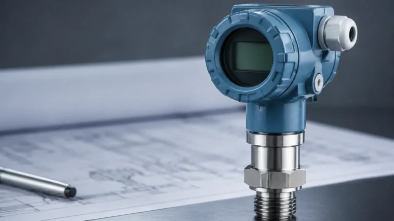
Tm111
Tm111
In the landscape of industrial automation and process control, the accuracy of level measurement is often dependent on auxiliary data points, most notably temperature. The TM111 series represents a critical category of industrial transmitters designed to convert raw sensor signals into standardized, interference-resistant outputs. Whether used as a standalone temperature transmitter or integrated into complex level measurement loops, understanding the technical nuances of the TM111 is essential for engineers aiming to maintain system integrity and data precision.
Industrial environments present significant challenges to signal transmission, including electromagnetic interference (EMI), long cable runs, and extreme thermal fluctuations. The TM111 addresses these challenges by providing a bridge between the primary sensing element and the control system (PLC/DCS). This article explores the measurement principles, technical specifications, and practical application of the TM111, particularly in its role supporting advanced level measurement solutions.
Core Measurement Principles and Signal Conversion
The TM111 functions primarily as a signal conditioner and transmitter. In most applications, it is paired with a Resistance Temperature Detector (RTD), such as a Pt100 or Pt1000, or a thermocouple. The fundamental principle involves the conversion of a non-linear resistance or millivolt signal into a linear 4-20mA current loop or a digital protocol like HART.
Resistance to Current Conversion
For RTD inputs, the TM111 measures the resistance of the platinum element, which changes predictably with temperature. To ensure accuracy, the transmitter typically employs a 3-wire or 4-wire compensation method. This is crucial because the resistance of the lead wires themselves can introduce significant errors if not accounted for. The TM111 electronics process this resistance value, linearize it according to international standards (such as IEC 60751), and output a current signal proportional to the programmed temperature range.
Thermocouple Signal Processing
When configured for thermocouples, the TM111 must handle extremely small millivolt signals. A key feature in this mode is Cold Junction Compensation (CJC). Since a thermocouple measures the temperature difference between the sensing tip and the connection point at the transmitter, the TM111 uses an internal sensor to measure the terminal temperature and mathematically corrects the output to provide an absolute temperature reading.
Signal Isolation and Stability
One of the primary reasons for using a TM111 rather than direct wiring to a PLC is galvanic isolation. High-quality TM111 units provide isolation between the input, output, and power supply. This prevents ground loops and protects sensitive control equipment from high-voltage surges that may occur in the field. This stability is a prerequisite for the reliable operation of the instruments found on the Main Page of industrial level sensing catalogs.
Technical Specifications and Evaluation Criteria
When selecting a TM111 for a specific project, engineers must evaluate several key performance indicators. These specifications determine the transmitter's suitability for the intended environment and its impact on the overall measurement uncertainty of the system.
| Feature | Specification Detail | Importance |
| :— | :— | :— |
| Input Types | Pt100, Pt1000, TC (Type K, J, T, E, N, R, S, B) | Versatility across different sensor types. |
| Accuracy | < 0.1% of span or ±0.1°C (0.18°F) | Minimizes the total error budget of the process loop. |
| Supply Voltage | 12V to 35V DC | Compatibility with standard industrial power rails. |
| Output Signal | 4-20mA, 2-wire / HART | Standardized communication with control systems. |
| Galvanic Isolation | 1.5 kV AC or higher | Protects against electrical noise and ground loops. |
| Response Time | < 1 second | Critical for fast-changing thermal processes. |
| Operating Temp | -40°C to +85°C (-40°F to +185°F) | Ensures reliability in outdoor or high-heat areas. |
Beyond these basic specs, the "Long-term Stability" (typically expressed as <0.1°C/year) is a vital metric. In level measurement applications where the transmitter might be mounted in a remote or inaccessible location, a low drift rate reduces the frequency of required calibrations.
Integration with Level Measurement Technologies
The TM111 is rarely an isolated component; it is frequently integrated into broader level measurement strategies. Many of the technologies offered by Welk, such as radar and ultrasonic sensors, rely on temperature data for maximum accuracy.
Compensation in Hydrostatic Level Measurement
Hydrostatic level transmitters calculate the height of a liquid based on the pressure exerted by the liquid column ($P = \rho gh$). However, the density ($\rho$) of most liquids changes with temperature. By integrating a TM111 to monitor the liquid temperature, the PLC can apply a real-time density correction factor. This is particularly important in the chemical and oil and gas industries, where even a 5°C (9°F) shift can result in significant volume calculation errors in large storage tanks.
Ultrasonic Velocity Correction
Ultrasonic level sensors measure the time-of-flight of sound waves. Since the speed of sound in air or gas varies significantly with temperature (approximately 0.6 m/s per degree Celsius), accurate temperature measurement is mandatory. While many ultrasonic sensors have built-in thermistors, an external TM111 paired with a high-precision RTD provides a more accurate reading of the gas space temperature, especially in tall silos where temperature gradients exist.
Radar Level Meter Support
In high-pressure or high-temperature steam applications, the dielectric constant of the vapor space can change. While radar is generally less affected by temperature than ultrasonic technology, extreme thermal conditions can still impact the electronics or the physical properties of the media. The TM111 provides the necessary environmental monitoring to ensure the radar unit operates within its specified thermal limits.
Installation Requirements and Wiring Standards
Proper installation of the TM111 is as important as the device's inherent accuracy. Failure to follow best practices can lead to signal degradation and premature hardware failure.
Mounting Options
1. Head Mounting: The TM111 is often designed in a puck-style format that fits directly into the connection head of a temperature sensor (DIN Form B). This minimizes the distance the low-level sensor signal must travel before being converted to 4-20mA.
2. DIN Rail Mounting: In centralized control cabinets, DIN rail versions are used. This allows for easier maintenance and protection from harsh process conditions, though it requires longer runs of compensated thermocouple wire or RTD extension wire.
Wiring and Shielding
To maintain the integrity of the 4-20mA loop, shielded twisted-pair cabling is recommended. The shield should be grounded at only one point (usually the control cabinet side) to avoid ground loops. For the input side, 3-wire RTD configurations are the industrial standard, as they allow the TM111 to mathematically cancel out the resistance of the lead wires, provided all three wires have the same length and gauge.
Environmental Protection
If the TM111 is mounted in the field, it must be housed in an enclosure with an appropriate Ingress Protection (IP) rating. For water treatment or outdoor chemical processing, an IP66 or IP67 rating is typically required to prevent moisture ingress. In hazardous areas (explosive atmospheres), the TM111 must be certified as Intrinsically Safe (Ex i) or Flameproof (Ex d).

Performance Limitations and Environmental Factors
While the TM111 is a robust instrument, it is not immune to environmental stressors. Engineers must be aware of the following limitations:
* Ambient Temperature Effect: Although the transmitter is designed to operate in a wide range, the internal electronics have a "temperature coefficient." This means the accuracy of the conversion may vary slightly if the transmitter itself is subjected to extreme heat or cold. High-quality units minimize this effect to less than 0.01% per degree.
* Electromagnetic Interference (EMI): In plants with large motors, variable frequency drives (VFDs), or high-voltage power lines, EMI can induce noise into the signal loop. The TM111 should be compliant with EMC standards (like EN 61326) to filter out this noise.
* Sensor Matching: The transmitter is only as accurate as the sensor it is connected to. For the highest precision, "sensor-transmitter matching" (using the Callendar-Van Dusen constants of a specific RTD) can be programmed into some advanced TM111 models to eliminate sensor-specific errors.
Frequently Asked Questions (FAQs)
Q: Can a TM111 be used with any RTD?
A: Most TM111 transmitters are universal and can be configured via PC software or HART communicators to accept Pt100, Pt500, or Pt1000 sensors. However, you must verify the input compatibility in the device datasheet.
Q: What is the benefit of a 4-20mA signal over a direct resistance signal?
A: A 4-20mA current loop is much more resistant to electrical noise and can travel over much longer distances (hundreds of meters) without the signal loss or resistance errors associated with raw RTD or thermocouple wires.
Q: How often should a TM111 be calibrated?
A: For most industrial applications, a calibration check every 12 to 24 months is sufficient. However, in highly regulated industries like pharmaceuticals or food processing, annual or semi-annual calibration may be required.
Q: Does the TM111 support digital communication?
A: Many versions of the TM111 include HART (Highway Addressable Remote Transducer) protocol support. This allows for digital configuration, diagnostics, and the transmission of secondary variables over the existing 4-20mA wiring.
Conclusion for Process Engineers
The TM111 serves as a foundational component in the modern industrial sensor ecosystem. By providing accurate, isolated, and standardized signal conversion, it ensures that critical temperature data is available for process control and level measurement compensation. When selecting a transmitter, engineers should prioritize accuracy, isolation, and environmental resilience to ensure long-term reliability. For further information on integrating these transmitters with radar, ultrasonic, or hydrostatic level sensors, professionals are encouraged to consult the comprehensive technical resources and product specifications available on the Main Page of the Welk instrument catalog. Proper selection and installation of the TM111 not only protect the control system but also significantly enhance the precision of the entire measurement loop.