Ultra Mag Meter
Ultra Mag Meter
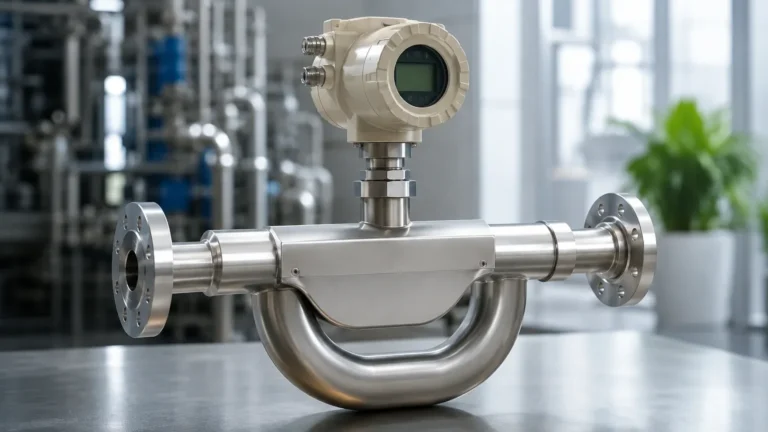
In the landscape of industrial fluid management, the electromagnetic flow meter, often referred to in high-performance contexts as the ultra mag meter, stands as a cornerstone technology for measuring the volumetric flow rate of conductive liquids. Unlike mechanical meters that rely on moving parts susceptible to wear and tear, the ultra mag meter utilizes electromagnetic properties to provide highly accurate, obstruction-free measurement. This guide explores the engineering principles, selection criteria, and practical installation requirements for these instruments, providing a comprehensive reference for process engineers and facility managers.
The Fundamental Measurement Principle of the Ultra Mag Meter
The operation of an ultra mag meter is governed by Faraday’s Law of Electromagnetic Induction. This principle states that a conductor moving through a magnetic field produces an electrical voltage proportional to the velocity of the conductor. In the context of flow measurement, the "conductor" is the process liquid itself.
How the Process Works
1. Magnetic Field Generation: The meter body contains a pair of electromagnetic coils. When energized, these coils generate a constant magnetic field across the cross-section of the pipe.
2. Fluid Movement: As a conductive liquid (such as water, wastewater, or chemical slurries) flows through the pipe, it passes through this magnetic field.
3. Voltage Induction: The movement of the liquid induces a voltage ($E$). This voltage is picked up by two electrodes mounted on opposite sides of the meter wall.
4. Signal Conversion: The induced voltage is directly proportional to the average flow velocity ($V$), the magnetic field strength ($B$), and the distance between the electrodes ($D$). The relationship is defined by the formula: $E = kBDV$, where $k$ is a constant. The transmitter then converts this voltage into a standardized flow rate signal (e.g., 4-20mA or digital output).
Because the measurement is independent of fluid density, viscosity, and pressure, the ultra mag meter is exceptionally versatile for various industrial applications, provided the medium meets a minimum threshold of electrical conductivity, typically $\geq 5 \mu S/cm$.
Critical Evaluation Criteria for High-Performance Mag Meters
When evaluating an ultra mag meter for a specific project, several technical specifications dictate the long-term reliability and accuracy of the device. High-performance models are distinguished by their construction materials and signal processing capabilities.
Liner Materials and Durability
The liner is the most critical component of the meter body, as it insulates the electrodes from the metal pipe and protects the meter from the process fluid. Common materials include:
* Fusion-Bonded Epoxy: Often found in high-end "ultra" models, this liner is applied as a powder and heat-cured, creating a seamless bond with the meter body. It is highly resistant to delamination and is frequently NSF-approved for potable water.
* PFA/PTFE: Ideal for high-temperature and highly corrosive chemical applications due to superior chemical resistance.
* Hard Rubber/Ebonite: Frequently used in large-diameter water mains and wastewater applications for its abrasion resistance.
Electrode Selection
Electrodes must be compatible with the chemical properties of the fluid. While 316L Stainless Steel is standard, aggressive media may require Hastelloy C, Tantalum, or Titanium to prevent corrosion and signal drift.
Accuracy and Rangeability
Standard electromagnetic meters offer accuracies of $\pm 0.5\%$ of reading. However, an ultra mag meter designed for precision billing or critical process control can achieve accuracies of $\pm 0.25\%$ or better. The turndown ratio—the range over which the meter maintains its accuracy—is typically 100:1 or higher, allowing for precise measurement during both peak and low-flow periods.
Industrial Applications: Where Precision Meets Durability
The robustness of the ultra mag meter makes it the preferred choice for sectors where fluid consistency varies or where maintenance access is limited.
Water and Wastewater Management
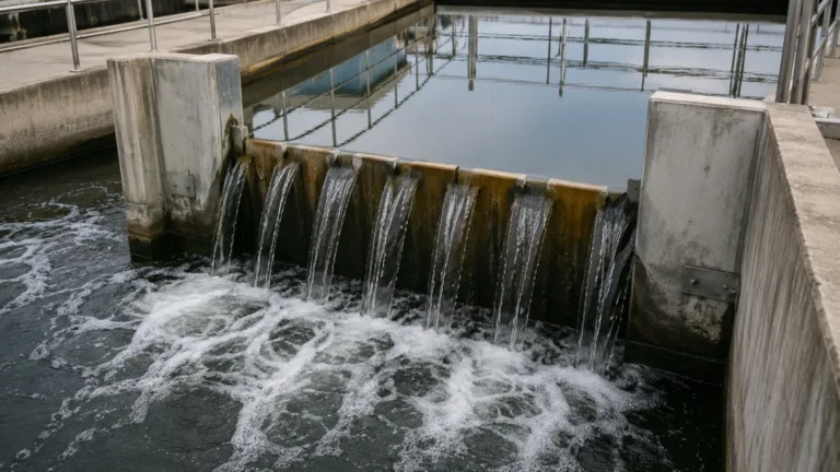
In municipal water treatment, these meters track influent and effluent flows, chemical dosing, and distribution system monitoring. Their ability to handle solids-bearing liquids without clogging is a significant advantage over turbine or vortex meters.
Industrial Process Water
Facilities utilizing cooling towers, boilers, and large-scale heat exchangers use mag meters to balance water loops. The absence of pressure drop across the meter helps maintain energy efficiency in high-volume pumping systems.
Agricultural Irrigation
For large-scale farming, the ultra mag meter provides accurate usage data for groundwater management and fertilizer injection (chemigation). Models with fusion-bonded epoxy liners are particularly valued here for their resistance to the abrasive sand and silt often found in well water.
For engineers looking to integrate these flow solutions with comprehensive tank management systems, reviewing the broader range of instrumentation on the Main Page can provide insights into how flow and level data work together for automated process control.
Selection Matrix: Comparing Electromagnetic Flow Meter Types
Choosing the right configuration depends on pipe size, budget, and required accuracy. The following table outlines the primary types of mag meters used in industrial settings.
| Feature | Full-Bore Mag Meter | Insertion Mag Meter | Low-Flow Mag Meter |
| :— | :— | :— | :— |
| Best Use Case | High-accuracy process control | Large pipes (> 500 mm), retrofits | Chemical dosing, lab scale |
| Accuracy | $\pm 0.25\%$ to $\pm 0.5\%$ | $\pm 1.0\%$ to $\pm 2.0\%$ | $\pm 0.5\%$ to $\pm 1.0\%$ |
| Installation | Requires pipe cutting/flanges | Hot-tap or single port | Threaded or small flange |
| Pressure Drop | Zero | Negligible | Minimal |
| Maintenance | Extremely low | Low (can be pulled under pressure) | Moderate |
| Typical Line Size | 15 mm to 2400 mm | 50 mm to 5000 mm | 2 mm to 20 mm |

Engineering Best Practices for Installation
Even the most advanced ultra mag meter will fail to provide accurate data if installed incorrectly. Electromagnetic meters are sensitive to flow profile disturbances and electrical interference.
Straight Pipe Requirements
To ensure a stable, laminar flow profile, mag meters generally require a straight run of pipe both upstream and downstream of the sensor. A common rule of thumb is 5D upstream and 2D downstream (where D is the pipe diameter). If the installation is near a pump or a partially open valve, these requirements may increase to 10D or more.
Grounding and Potential Equalization
Because the meter measures micro-voltages, it is essential that the fluid, the meter body, and the transmitter share the same electrical potential.
* Conductive Pipes: The meter can be grounded directly to the metal flanges.
* Plastic/Lined Pipes: Grounding rings (or a third "grounding electrode" within the meter) must be used to provide a path to the fluid, preventing stray currents from interfering with the flow signal.
Orientation and Filling
The meter must always be installed in a location where the pipe remains 100% full.
* Vertical Upward Flow: This is the ideal orientation, as it ensures the pipe is full and helps prevent the entrapment of air bubbles.
* Horizontal Flow: The electrodes should be positioned at the 3 o'clock and 9 o'clock positions to avoid interference from sediment at the bottom or air pockets at the top of the pipe.
Limitations and Common Operational Risks
While highly versatile, the ultra mag meter is not a universal solution. Engineers must be aware of specific limitations to avoid equipment failure.
1. Non-Conductive Fluids: Mag meters cannot measure hydrocarbons (oils, fuels), distilled water, or gases. If the conductivity drops below the manufacturer's specified limit, the signal will become unstable or disappear.
2. Vacuum Conditions: In certain piping configurations, a vacuum can form. If the meter is not rated for vacuum service, the liner can collapse or pull away from the pipe wall, leading to catastrophic failure.
3. Electrode Coating: In applications involving sticky or oily substances (such as raw sewage or certain food products), a film can build up over the electrodes. This acts as an insulator, causing the meter to under-read. Selecting a meter with "bullet-shaped" electrodes or self-cleaning circuitry can mitigate this risk.
4. Ambient Interference: High-voltage cables or large motors located in close proximity to the meter can induce noise into the signal. Proper shielding of the signal cable is mandatory.
Frequently Asked Questions (FAQ)
What is the minimum conductivity required for an ultra mag meter?
Most industrial mag meters require a minimum conductivity of $5 \mu S/cm$. Some specialized electronics can handle fluids down to $1 \mu S/cm$, but standard potable water (typically $50-500 \mu S/cm$) is well within the operating range.
Can an ultra mag meter measure flow in both directions?
Yes, most modern electromagnetic meters are inherently bi-directional. They can be configured to track totalized flow for both forward and reverse directions, which is particularly useful in reservoir management and complex distribution networks.
How often does the meter need to be calibrated?
Because there are no moving parts to wear out, the physical sensor is extremely stable. However, many regulatory bodies and quality standards (like ISO 9001) require an annual electronics verification. This can often be done "in-situ" using a handheld simulator without removing the meter from the line.
What happens if air bubbles are present in the liquid?
Air bubbles are non-conductive. The mag meter will treat the volume of the bubble as part of the liquid volume, leading to an over-reading of the actual liquid flow. If significant air is expected, an air eliminator should be installed upstream of the meter.
Is the ultra mag meter suitable for high-pressure applications?
Yes, provided the flange rating and the meter body construction match the system requirements. High-pressure versions can be engineered to handle 40 bar (approx. 580 psi) or higher, depending on the nominal diameter.
By understanding these technical nuances, engineers can ensure that the ultra mag meter provides the reliable, long-term data necessary for efficient industrial operations. For further technical specifications and to explore how these flow instruments integrate with level measurement technologies, refer to the resources available on the Main Page.