Ultramag Flow Meter
Ultramag Flow Meter
In the landscape of industrial process control, the accurate measurement of liquid flow is as critical as the monitoring of tank levels. The ultramag flow meter, a specialized category of electromagnetic flow meter, represents a cornerstone technology for handling conductive liquids, slurries, and corrosive chemicals. While level measurement instruments—such as those found on our Main Page—provide data on volume and inventory, flow meters provide the dynamic data necessary for real-time process regulation, dosing, and custody transfer. Understanding the operational physics, material constraints, and installation requirements of these meters is essential for any engineering team tasked with optimizing industrial fluid systems.
Measurement Principle: Faraday’s Law of Induction
The ultramag flow meter operates based on Faraday’s Law of Electromagnetic Induction. This principle dictates that a conductor moving through a magnetic field generates an electromotive force (voltage) proportional to its velocity. In the context of a flow meter, the liquid itself acts as the conductor.
The Mathematical Foundation
The relationship is expressed by the equation:
E = B × v × D
Where:
* E is the induced voltage (signal).
* B is the strength of the magnetic field generated by the internal coils.
* v is the average velocity of the liquid.
* D is the internal diameter of the pipe (the distance between electrodes).
Because the magnetic field (B) and the pipe diameter (D) are constants within a specific meter body, the induced voltage is directly and linearly proportional to the flow velocity (v). This allows the ultramag flow meter to provide highly accurate readings across a wide turndown ratio, often exceeding 100:1. Unlike mechanical meters, there are no moving parts in the flow stream, which eliminates pressure drops and reduces the risk of mechanical wear.
Key Components and Construction
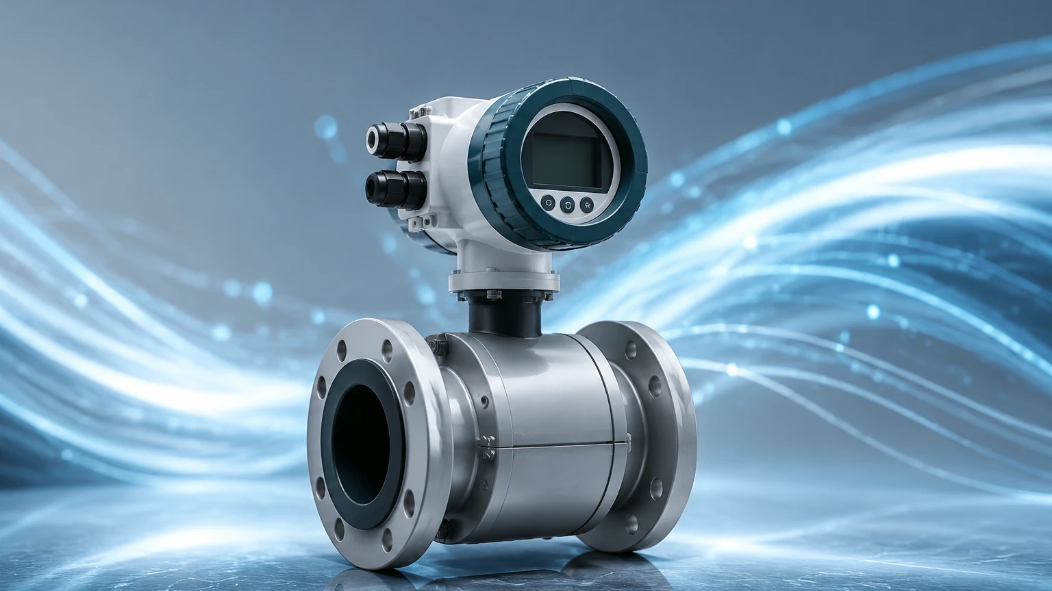
To withstand the harsh environments of chemical processing and wastewater management, the construction of an ultramag flow meter involves several critical sub-assemblies:
1. The Flow Tube: Usually constructed from non-magnetic stainless steel to prevent interference with the magnetic field.
2. The Liner: An insulating material that prevents the induced voltage from shorting out against the metal flow tube. Common materials include PTFE, PFA, and Hard Rubber.
3. Electromagnetic Coils: Located outside the liner, these generate the stable magnetic field across the pipe cross-section.
4. Electrodes: Typically made of corrosion-resistant metals like Hastelloy C, Tantalum, or Titanium, these pick up the micro-volt signal from the fluid.
5. The Transmitter: The "brain" of the unit, which filters noise, amplifies the signal, and converts it into a standard industrial output (e.g., 4-20mA, Modbus, or HART).
Technical Selection Criteria
Selecting the correct ultramag flow meter requires a detailed analysis of the process fluid and the mechanical environment. The following tables provide a baseline for engineering selection.
Table 1: Liner Material Compatibility
| Liner Material | Temperature Range | Typical Applications |
| :— | :— | :— |
| PTFE (Teflon) | -20°C to +120°C | Strong acids, bases, and high-purity chemicals. |
| PFA | -20°C to +180°C | High-temperature corrosive fluids; excellent vacuum resistance. |
| Hard Rubber | 0°C to +80°C | General water treatment, wastewater, and mildly abrasive slurries. |
| Polyurethane | -10°C to +60°C | Highly abrasive slurries, mining applications, and sand-water mixes. |
Table 2: Electrode Material Selection
| Electrode Material | Chemical Resistance |
| :— | :— |
| 316L Stainless Steel | Low-corrosion liquids, potable water, and organic solvents. |
| Hastelloy C | Seawater, chloride solutions, and oxidizing acids. |
| Titanium | Nitric acid, chromic acid, and specific brine solutions. |
| Tantalum | Most concentrated acids (except Hydrofluoric acid). |
| Platinum-Iridium | Extreme chemical resistance for specialized laboratory or pharmaceutical use. |
Practical Selection and Sizing
When sizing an ultramag flow meter, the goal is to maintain a fluid velocity that is high enough to ensure accuracy but low enough to prevent excessive liner wear or pressure loss. The ideal velocity range for most electromagnetic meters is between 2 m/s and 6 m/s, though they can operate accurately from 0.3 m/s to 10 m/s.
Flow Rate Reference Table (Metric)
| Nominal Diameter (mm) | Min Flow (m³/h) @ 0.5 m/s | Max Flow (m³/h) @ 10 m/s |
| :— | :— | :— |
| DN25 | 0.88 | 17.6 |
| DN50 | 3.53 | 70.6 |
| DN100 | 14.13 | 282.7 |
| DN200 | 56.54 | 1,130.9 |
| DN500 | 353.43 | 7,068.5 |
If the existing pipe diameter results in a velocity below 0.3 m/s, engineers often use a "reducer" pipe configuration to increase velocity through the meter body, thereby improving the signal-to-noise ratio.
Installation Considerations
To maintain the accuracy specified by the manufacturer (typically ±0.5% or better), the ultramag flow meter must be installed according to strict hydraulic guidelines. The primary objective is to ensure a fully developed, symmetrical flow profile as the liquid enters the magnetic field.
Straight Pipe Requirements
Standard installations require a minimum of 5D (five times the pipe diameter) of straight pipe upstream of the meter and 2D of straight pipe downstream. If a valve or pump is located immediately upstream, this requirement may increase to 10D to dissipate turbulence.
Orientation and Fluid Integrity
* Vertical Installation: This is the preferred orientation, with the flow moving upward. This ensures that the pipe remains full of liquid and prevents air bubbles from collecting at the electrodes.
* Horizontal Installation: The meter must be placed in a low point of the piping system (a "U" trap) to ensure the pipe is always full. The electrode axis must be horizontal to prevent air bubbles (at the top) or sediment (at the bottom) from insulating the electrodes.
* Grounding: Since the induced voltage is often in the millivolt range, proper grounding is non-negotiable. Grounding rings are required if the adjacent piping is plastic or lined with an insulating material.
Limitations and Common Risks
While highly versatile, the ultramag flow meter is not a universal solution. Engineers must be aware of the following limitations:
1. Conductivity Threshold: The fluid must have a minimum conductivity, typically >5 μS/cm. Consequently, these meters cannot measure hydrocarbons (oils), distilled water, or gases.
2. Vacuum Conditions: In systems where a vacuum may occur, certain liners (like PTFE) can collapse or peel away from the tube wall. PFA liners with stainless steel mesh reinforcement are required for vacuum service.
3. Entrained Air: Large bubbles or slugs of air will cause the meter to read inaccurately or "spike," as the air is non-conductive and disrupts the magnetic circuit.
4. Coating and Scaling: If the process fluid tends to deposit minerals or fats, the electrodes may become coated over time, leading to signal loss. In these cases, meters with "removable electrodes" or ultrasonic cleaning circuits are recommended.
Integration with Level Measurement Systems
In many industrial applications, flow and level data are used in tandem. For example, in a chemical dosing tank, a radar level sensor monitors the total inventory while an ultramag flow meter regulates the precise amount of chemical being discharged into the process. This dual-point monitoring allows for mass balance calculations and leak detection.
Welk provides a comprehensive range of level measurement solutions that complement flow instrumentation. By integrating high-accuracy level transmitters with reliable flow data, operators can achieve a holistic view of their automation environment. For more information on our level measurement technologies, please visit our Main Page.
Frequently Asked Questions (FAQ)
Q: Can an ultramag flow meter measure flow in both directions?
A: Yes, most modern electromagnetic transmitters are bi-directional. They can be configured to provide separate totalizers for forward and reverse flow, which is particularly useful in water distribution networks.
Q: How often does the meter require calibration?
A: Because there are no moving parts to wear out, the physical "drift" of the sensor is minimal. However, many industries (such as food and pharma) require annual verification. This can often be done using electronic simulators without removing the meter from the line.
Q: What happens if the pipe is only half full?
A: The meter will provide an inaccurate, usually higher-than-actual reading because it assumes the entire cross-sectional area (D) is filled with moving liquid. For partially filled pipes, specialized "partially filled" mag meters with integrated level sensors must be used.
Q: Is the meter affected by changes in viscosity or density?
A: No. One of the primary advantages of the electromagnetic principle is that it is independent of fluid viscosity, density, and pressure, provided the fluid remains conductive and the flow is sub-sonic.
Conclusion
The ultramag flow meter is an indispensable tool for modern industrial fluid management. By leveraging Faraday's Law, it offers a non-invasive, highly accurate, and low-maintenance solution for measuring conductive liquids. When paired with robust level measurement strategies, these instruments ensure that process plants operate with maximum efficiency and minimal waste. For technical support in selecting the right measurement instruments for your specific application, explore the resources available on our Main Page.