Ultrasonic Clamp-on Flow Meters
Ultrasonic Clamp-on Flow Meters
In the landscape of industrial process control, the ability to measure fluid velocity without breaching the integrity of a piping system represents a significant operational advantage. Ultrasonic clamp-on flow meters have emerged as a primary solution for facilities seeking to avoid the costs and risks associated with pipe cutting, welding, and process downtime. These instruments utilize acoustic signals to determine flow rates, offering a non-invasive alternative to traditional inline meters like electromagnetic or turbine devices.
For engineering teams and plant managers, understanding the underlying physics and the specific application constraints of ultrasonic technology is essential for ensuring long-term accuracy. While these meters are highly versatile, their performance is heavily dependent on the interaction between the acoustic transducers, the pipe wall, and the fluid dynamics within the conduit.
Measurement Principles: Transit-Time vs. Doppler
Ultrasonic flow measurement typically relies on one of two distinct physical principles: Transit-Time or the Doppler Effect. Selecting the correct principle is the first step in any procurement process, as the choice depends entirely on the characteristics of the fluid being measured.
Transit-Time Ultrasonic Flow Meters
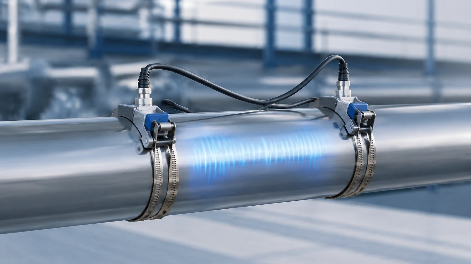
Transit-time technology is the most common method for clean liquids. The system uses a pair of transducers (A and B) that function as both transmitters and receivers. Transducer A sends an ultrasonic pulse to Transducer B, and then Transducer B sends a pulse back to Transducer A.
When the fluid is stationary, the time taken for the signal to travel in both directions is identical. However, when fluid is flowing, the pulse traveling with the flow (downstream) moves faster than the pulse traveling against the flow (upstream). The meter measures this time difference—often in the nanosecond range—to calculate the velocity of the fluid. Because the speed of sound in the fluid varies with temperature and pressure, modern electronics must compensate for these variables to maintain accuracy. This method is ideal for treated water, chemicals, and refined oils where the liquid is relatively free of suspended solids or entrained air.
Doppler Ultrasonic Flow Meters
Doppler flow meters operate on the principle of frequency shift. The transmitter sends an ultrasonic signal of a known frequency into the pipe. This signal reflects off "discontinuities" in the fluid—such as suspended solids, gas bubbles, or turbulent eddies. Because these particles are moving at the same velocity as the fluid, the reflected signal returns to the receiver at a shifted frequency.
This frequency shift (the Doppler Effect) is directly proportional to the flow velocity. Unlike transit-time meters, Doppler meters require a minimum concentration of particles or bubbles (typically at least 100 parts per million of 75-micron sized particles) to function. They are the preferred choice for wastewater, slurries, and aerated liquids where transit-time signals would be scattered or absorbed.
Key Evaluation Criteria for Selection
When evaluating ultrasonic clamp-on flow meters for a specific project, several technical parameters must be confirmed to ensure compatibility. Engineering specifications should focus on the following criteria:
Pipe Material and Condition
The acoustic signal must pass through the pipe wall twice (or more, depending on the mounting method). Materials with high acoustic conductivity, such as carbon steel, stainless steel, and most plastics (PVC, PE), are excellent candidates. However, pipes with internal linings—such as cement, rubber, or thick bitumen—can pose challenges if the lining is not perfectly bonded to the pipe wall. Any air gap between the lining and the pipe will reflect the ultrasonic signal, preventing it from reaching the fluid.
Fluid Properties
For transit-time meters, the fluid must be sonically conductive and relatively clean. High concentrations of solids or bubbles will attenuate the signal. Furthermore, the fluid's kinematic viscosity affects the flow profile (laminar vs. turbulent). Most high-end meters include a Reynolds number compensation algorithm to adjust for these profile changes automatically.
Temperature Ranges
Standard transducers typically handle temperatures up to 80°C (176°F). For high-temperature applications, such as steam condensate or hot oil loops, specialized high-temperature transducers and mounting rails are required to protect the piezoelectric elements from thermal degradation.
Practical Selection Table
The following table provides a general guideline for choosing between transit-time and Doppler technologies based on common industrial fluid types.
| Fluid Type | Recommended Technology | Typical Accuracy | Key Consideration |
| :— | :— | :— | :— |
| Potable Water | Transit-Time | 0.5% to 2.0% | Ensure pipe is full. |
| Deionized/Pure Water | Transit-Time | 0.5% | Very high signal strength. |
| Raw Sewage/Sludge | Doppler | 2.0% to 5.0% | Requires >100ppm solids. |
| Chemical Acids/Alums | Transit-Time | 1.0% | Verify pipe material compatibility. |
| Crude Oil | Transit-Time | 1.0% | Monitor viscosity changes. |
| Aerated Mining Slurries | Doppler | 3.0% | High wear on pipe interior. |
Installation Considerations and Mounting Methods
The accuracy of a clamp-on meter is only as good as its installation. Because the sensors are not in direct contact with the fluid, the physical alignment and the quality of the acoustic coupling are paramount.
Straight Pipe Requirements
To achieve a stable flow profile, ultrasonic meters require a specific length of straight pipe upstream and downstream of the installation point. The standard recommendation is 10 pipe diameters (10D) upstream and 5 pipe diameters (5D) downstream. If the installation is near a pump or a partially open valve, these requirements may increase to 20D or 30D to mitigate turbulence.
Mounting Configurations
There are three primary ways to mount transducers on a pipe:
1. V-Method: The signals reflect once off the opposite pipe wall. This is the standard for pipe diameters ranging from 25mm to 400mm. It provides a good balance between signal strength and path length.
2. Z-Method: The transducers are mounted on opposite sides of the pipe, and the signal passes through the fluid only once. This is used for large pipes (typically >400mm) or when the fluid is highly attenuative, as it offers the strongest signal reception.
3. W-Method: The signal reflects three times before reaching the receiver. This is reserved for very small pipes (usually below 50mm) where a longer transit path is needed to achieve measurable time differences.
Acoustic Coupling
An acoustic coupling agent (grease or gel) must be applied between the transducer face and the pipe wall to eliminate any air gaps. In permanent installations, solid coupling pads or high-temperature silicone may be used. It is critical to remove any loose scale, rust, or thick paint from the pipe surface before mounting to ensure the signal can penetrate the wall.
Limitations and Common Risks
While ultrasonic clamp-on flow meters offer significant convenience, they are not universal solutions. Engineers must be aware of specific limitations:
* Pipe Wall Thickness: Accurate measurement requires precise knowledge of the pipe's wall thickness. If the thickness is unknown or varies due to internal corrosion, the meter’s calculation of the internal diameter—and thus the flow rate—will be incorrect. Using an ultrasonic thickness gauge prior to installation is highly recommended.
* Partially Filled Pipes: These meters are designed for pipes that are 100% full. If a pipe is partially full, the acoustic path may be broken, or the meter may calculate flow based on a cross-sectional area that is larger than the actual fluid volume.
* Signal Interference: High-frequency noise from nearby variable frequency drives (VFDs) or heavy machinery can sometimes interfere with the sensitive electronics of the flow meter. Shielded cabling and proper grounding are essential.
Integration with Industrial Automation
In modern industrial environments, flow measurement is rarely an isolated data point. It is often integrated into broader process control systems alongside level measurement and pressure monitoring. For instance, in a water treatment facility, monitoring the flow rate into a tank via a clamp-on meter while simultaneously tracking the tank level using a radar or ultrasonic level sensor allows for precise mass balance calculations and leak detection.
Reliable instrumentation is the foundation of these automated systems. For professionals looking to optimize their process loops, it is helpful to Review product options and application support to ensure that the chosen flow and level instruments are compatible with the specific environmental conditions of the site.
Frequently Asked Questions (FAQ)
Q: Can ultrasonic clamp-on flow meters measure gas flow?
A: While most clamp-on meters are designed for liquids, specialized high-power ultrasonic meters exist for high-pressure gas applications. However, standard liquid meters will not work on gas because the acoustic impedance of gas is too low to allow the signal to pass effectively from the pipe wall into the medium.
Q: How often do the transducers need to be recalibrated?
A: The transducers themselves do not have moving parts and rarely drift. However, the coupling gel can dry out over several years, leading to signal loss. A periodic check of the signal strength and a re-application of couplant every 2–3 years is a common maintenance practice.
Q: Does the pipe material affect accuracy?
A: Yes. The meter must know the "speed of sound" in the pipe material to calculate the refraction angle of the signal. Most meters come with a pre-programmed library of materials (Steel, Plastic, Copper, etc.). If the material is an unknown alloy, the accuracy may be compromised unless the material's sonic properties are manually entered.
Q: What is the minimum flow velocity required?
A: Most ultrasonic meters can detect velocities as low as 0.01 m/s, making them much more sensitive to low-flow conditions than mechanical meters. Their upper limit is typically around 12 to 15 m/s.
By following these technical guidelines and carefully assessing the pipe and fluid conditions, ultrasonic clamp-on flow meters provide a reliable, cost-effective, and highly flexible solution for industrial fluid management.