Clamp-on Ultrasonic Flow Meter
Clamp-on Ultrasonic Flow Meter
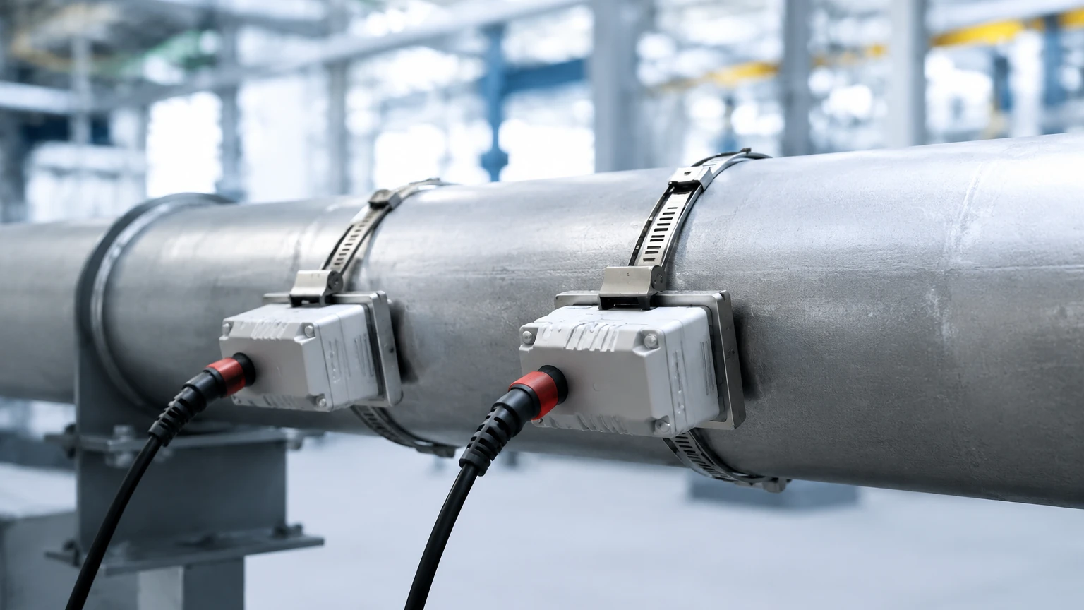
In modern industrial process control, the ability to measure fluid velocity without interrupting production or compromising the integrity of the piping system is a significant operational advantage. The clamp-on ultrasonic flow meter has emerged as a primary solution for such requirements. Unlike traditional inline flow meters that require pipe cutting and flange installation, clamp-on sensors are mounted externally. This non-invasive approach is particularly valuable in water treatment, chemical processing, and oil and gas industries where downtime and leakage risks must be minimized.
As a professional manufacturer of industrial measurement instruments, Welk provides high-precision solutions that integrate seamlessly into automated systems. While level measurement remains a core focus for tank management, flow measurement provides the necessary data for mass balance and system efficiency. For detailed specifications on integrated measurement systems, engineers can visit the Main Page to review product options and application support.
Principles of Ultrasonic Flow Measurement
Understanding the physics behind ultrasonic technology is essential for correct device selection and installation. Clamp-on ultrasonic flow meters generally operate based on one of two primary principles: Transit-Time or Doppler Effect.
Transit-Time Method
This is the most common method used for clean liquids. It relies on the principle that sound waves travel faster when moving in the direction of the flow and slower when moving against it. Two transducers function as both transmitters and receivers. They are placed on the outside of the pipe at a specific distance.
1. Upstream Transmission: The upstream transducer sends a signal to the downstream transducer.
2. Downstream Transmission: The downstream transducer sends a signal back to the upstream transducer.
3. Time Difference: The meter measures the time difference (delta-T) between these two signals. If there is no flow, the travel times are identical. As flow increases, the difference grows proportionally to the fluid velocity.
Doppler Effect Method
The Doppler method is utilized for fluids containing suspended solids, bubbles, or high turbidity. It works by transmitting an ultrasonic signal into the pipe, which then reflects off particles or bubbles moving with the fluid. The frequency of the reflected signal is shifted relative to the original signal. This frequency shift is directly proportional to the flow velocity. While less accurate than transit-time for clean water, it is indispensable for wastewater and mining slurries.
Key Evaluation Criteria for Industrial Applications
Selecting a clamp-on ultrasonic flow meter requires a thorough assessment of the application environment. Because the signal must pass through the pipe wall, the physical properties of the installation site are as important as the fluid itself.
Pipe Material and Condition
The pipe must be a good conductor of ultrasonic waves. Materials such as carbon steel, stainless steel, cast iron, and most plastics (PVC, PE, HDPE) are compatible. However, pipes with internal liners (such as cement, rubber, or glass) can present challenges if there is an air gap between the liner and the pipe wall. Furthermore, excessive internal scaling or external corrosion can attenuate the signal, leading to measurement errors.
Fluid Characteristics
For transit-time meters, the fluid should ideally contain less than 2% total suspended solids (TSS) or aeration. If the fluid is a heavy slurry or contains significant gas bubbles, a Doppler-based meter is required. Temperature also plays a role; standard transducers usually handle up to 80°C (176°F), while high-temperature variants are required for processes exceeding 150°C (302°F).
Accuracy and Rangeability
Most high-quality clamp-on meters offer an accuracy of ±1% to ±2% of the flow rate after proper calibration. They excel in wide turndown ratios, often capable of measuring velocities from as low as 0.01 m/s to over 12 m/s (0.03 to 40 ft/s). This makes them suitable for detecting leaks in low-flow conditions as well as monitoring high-velocity pump discharges.
Installation Best Practices and Mounting Methods
The performance of a clamp-on ultrasonic flow meter is heavily dependent on the quality of the installation. Unlike level meters that might only require a clear vertical path, flow meters require specific hydraulic conditions.
Straight Pipe Run Requirements
To ensure a stable flow profile, the transducers must be installed on a straight section of pipe. The standard engineering guideline is "10D Upstream and 5D Downstream." This means there should be a straight pipe length equal to 10 times the pipe diameter before the sensors and 5 times the diameter after them. If there are valves, pumps, or multiple elbows nearby, these distances may need to increase to 20D or 30D to avoid turbulence.
Mounting Configurations
Depending on the pipe diameter and fluid properties, three mounting methods are typically used:
* V-Method: The most common for pipe diameters ranging from DN25 to DN400 (1" to 16"). The signal bounces off the opposite pipe wall once. It is easy to install and provides good accuracy.
* Z-Method: Used for large pipes (typically above DN400) or where the fluid is highly attenuative. The transducers are placed on opposite sides of the pipe, and the signal crosses the pipe once. This provides the strongest signal strength.
* W-Method: Used for very small pipes (typically below DN50). The signal bounces three times before reaching the receiver, increasing the path length and improving resolution for low-flow detection.
Acoustic Coupling
Because air is a poor conductor of high-frequency sound, an acoustic coupling agent (grease or gel) must be applied between the transducer face and the pipe surface. For permanent installations, silicone-based couplants or solid foil pads are used to prevent the interface from drying out over time.
Technical Specifications and Selection Table
When evaluating hardware, engineers should compare the following parameters to ensure the device meets the project's technical boundaries.
| Feature | Transit-Time Clamp-On | Doppler Clamp-On |
| :— | :— | :— |
| Primary Fluid Type | Clean liquids, water, oils | Slurries, wastewater, aerated liquids |
| Pipe Size Range | DN15 to DN6000 | DN25 to DN6000 |
| Accuracy | ±0.5% to ±2.0% of reading | ±2.0% to ±5.0% of reading |
| Repeatability | 0.2% | 0.5% |
| Output Options | 4-20mA, Pulse, Modbus RTU, HART | 4-20mA, Pulse, Relay |
| Power Supply | 24V DC, 220V AC, or Battery | 24V DC or 220V AC |
| Installation Effort | Low (No pipe cutting) | Low (No pipe cutting) |
Limitations and Operational Risks
While the clamp-on ultrasonic flow meter is highly versatile, it is not a universal solution for every process. Engineers must be aware of the following limitations:
1. Signal Attenuation: In very old pipes, thick layers of rust or tuberculation can absorb the ultrasonic signal, making measurement impossible. In such cases, the pipe surface must be ground down to shiny metal before mounting.
2. Pipe Wall Thickness Knowledge: The meter calculates flow based on the internal diameter. If the wall thickness entered into the transmitter is incorrect, the resulting flow calculation will be skewed. Using an ultrasonic thickness gauge is recommended before flow meter setup.
3. Partially Filled Pipes: Ultrasonic flow meters require the pipe to be completely full (100% liquid). If the pipe is partially full, the sound wave will reflect off the liquid-air interface, leading to erratic readings or a "Signal Lost" error.
4. Ambient Noise: High-frequency mechanical noise from nearby variable frequency drives (VFDs) or heavy machinery can sometimes interfere with the ultrasonic signal. Using shielded cables and proper grounding is mandatory.
Frequently Asked Questions (FAQs)
Q: Can a clamp-on meter measure flow in both directions?
A: Yes, transit-time meters are inherently bi-directional. They can measure and totalize flow in both upstream and downstream directions, which is useful for storage tank loading and unloading applications.
Q: How often does the coupling gel need to be replaced?
A: For temporary surveys, standard gel lasts a few days. For permanent installations, specialized high-temperature grease or adhesive pads can last several years. If signal strength drops over time, the couplant is the first thing to check.
Q: Does the pipe material affect the sound speed?
A: Yes, the meter's software includes a database of sound speeds for various materials (Steel, Copper, PVC, etc.). Selecting the correct material is vital for the meter to calculate the correct transducer spacing.
Q: Can it measure gas flow?
A: Standard liquid clamp-on meters cannot measure gas. Gas flow requires much higher frequency transducers and different signal processing due to the low density of the medium. Welk focuses primarily on liquid measurement solutions.
Conclusion
The clamp-on ultrasonic flow meter represents a cost-effective and reliable choice for modern industrial facilities looking to upgrade their monitoring capabilities without the expense of piping modifications. By understanding the transit-time principle and adhering to strict installation guidelines regarding straight pipe runs and acoustic coupling, operators can achieve high-precision data for process optimization.
For engineers managing complex liquid systems, combining accurate flow data with reliable level measurement is the key to total process transparency. To explore a full range of industrial measurement instruments, including radar and ultrasonic sensors, visit the Main Page for comprehensive product information and technical support.