Ultrasonic Flow Detector
Ultrasonic Flow Detector
In the landscape of industrial process control, the ultrasonic flow detector has emerged as a cornerstone technology for non-invasive fluid measurement. Unlike traditional mechanical flow meters that require cutting into pipes or introducing moving parts into the flow stream, ultrasonic technology utilizes acoustic waves to determine velocity. This approach minimizes maintenance requirements, eliminates pressure drops, and prevents potential leak points, making it a preferred choice for high-purity, corrosive, or high-pressure applications.
As a professional manufacturer of industrial measurement instruments, Welk provides high-precision solutions across various sectors, including water treatment, chemical processing, and oil and gas. Understanding the operational physics and selection criteria of an ultrasonic flow detector is essential for engineers tasked with optimizing plant efficiency and ensuring regulatory compliance.
Measurement Principles: Transit-Time vs. Doppler Effect
Before selecting an instrument, it is critical to understand the two primary physical principles used in ultrasonic flow detection. The choice between them depends entirely on the characteristics of the fluid being measured.
1. Transit-Time Principle
Transit-time ultrasonic flow detectors operate by sending and receiving ultrasonic pulses between two transducers. One transducer is located upstream and the other downstream. When the fluid is at a standstill, the time taken for a pulse to travel from the upstream sensor to the downstream sensor is identical to the time taken for the reverse path.
When fluid flows, the pulse traveling with the flow moves faster, while the pulse traveling against the flow moves slower. The flow velocity ($V$) is proportional to the difference in these travel times ($Δt$). This method is highly accurate for clean liquids with low concentrations of suspended solids or entrained gases (typically less than 1% to 2% by volume).
2. Doppler Effect Principle
Doppler flow detectors rely on the frequency shift of an ultrasonic signal reflected off moving discontinuities within the fluid. These discontinuities can be suspended solids, sediment, or gas bubbles. The transducer transmits a signal of a known frequency; as the signal hits a moving particle, it reflects back to the receiver with a frequency shift ($Δf$) proportional to the velocity of the particle.
This method is ideal for "dirty" liquids, slurries, or aerated fluids where transit-time signals would be scattered or absorbed. It is widely used in wastewater management and mining applications.
Key Components of an Ultrasonic Flow System
A standard ultrasonic flow detector system consists of three primary elements:
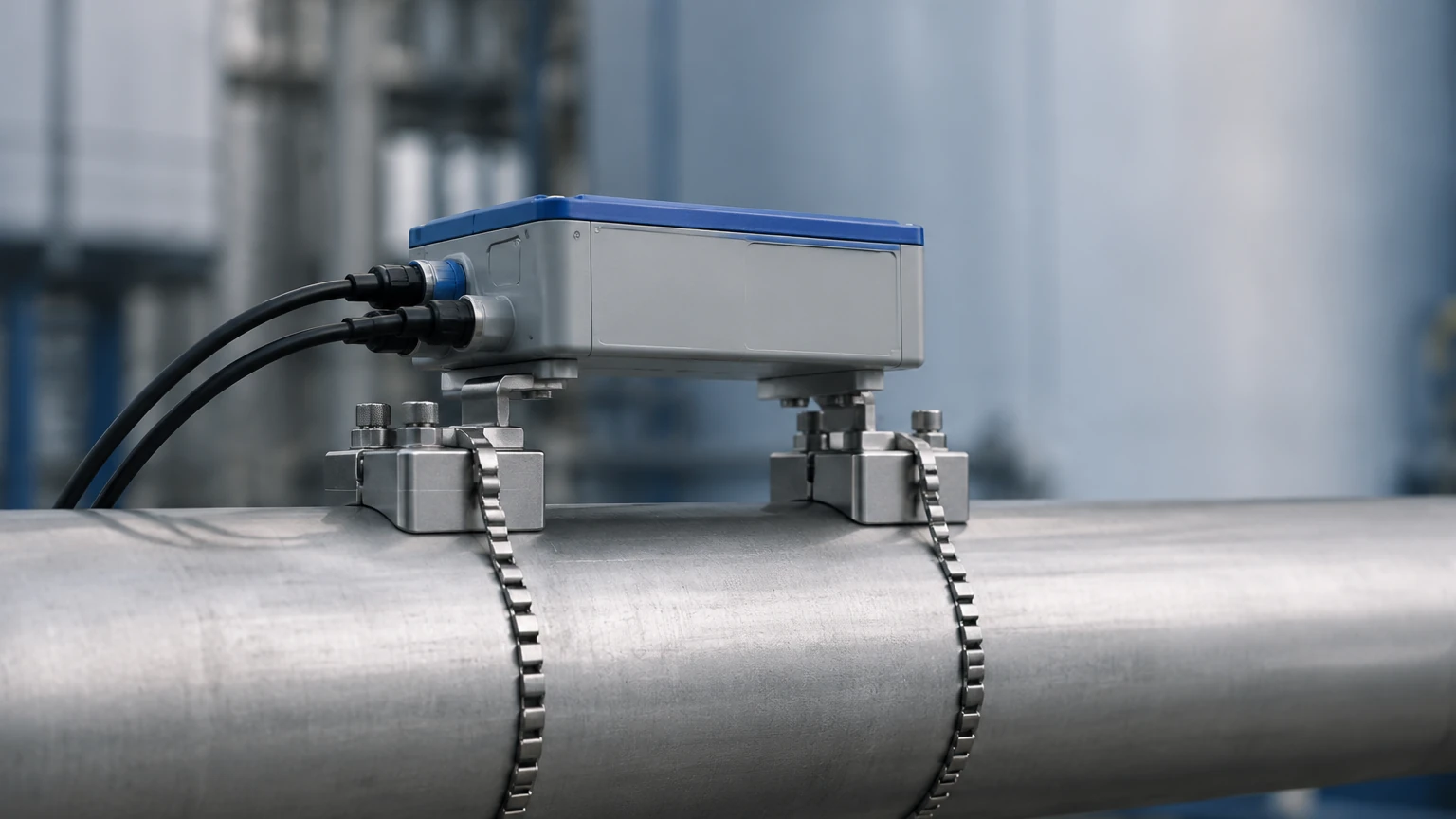
1. Transducers (Sensors): These contain piezoelectric crystals that convert electrical energy into ultrasonic vibrations (and vice versa). They can be "clamp-on" (mounted to the outside of the pipe) or "wetted/insertion" (contacting the fluid).
2. Signal Processor (Transmitter): This unit powers the transducers, processes the acoustic data, and calculates the flow rate based on programmed pipe parameters (diameter, material, wall thickness).
3. Output Interface: Most modern detectors provide 4-20mA analog outputs, pulse outputs for totalization, and digital protocols such as RS485 (Modbus) or HART for integration into PLC and SCADA systems.
Practical Selection Criteria
Choosing the right ultrasonic flow detector requires a detailed analysis of the application environment. The following table provides a comparison to guide the initial selection process.
Selection Matrix
| Feature | Transit-Time Detector | Doppler Effect Detector |
| :— | :— | :— |
| Fluid Type | Clean liquids (Water, oils, chemicals) | Aerated or dirty liquids (Sewage, slurries) |
| Suspended Solids | < 2% by volume | > 100 ppm (parts per million) |
| Accuracy | High (±0.5% to ±1% of velocity) | Moderate (±2% to ±5% of velocity) |
| Pipe Sizes | 10 mm to 6000 mm | 25 mm to 3000 mm |
| Primary Advantage | High precision in clean fluids | Ability to measure highly turbid fluids |
| Limitation | Fails if bubbles/solids are too high | Fails in ultra-pure water |
For comprehensive system design, engineers should also consult the Main Page of reputable manufacturers to review specific model tolerances and chemical compatibility charts.
Installation Guidelines and Best Practices
The performance of an ultrasonic flow detector is heavily dependent on the quality of the installation. Because these meters rely on stable flow profiles, turbulence is the primary enemy of accuracy.
Straight Pipe Run Requirements
To ensure a fully developed laminar flow profile, the sensors must be installed on a straight section of pipe. The standard industry recommendation is:
* Upstream: Minimum 10D (10 times the nominal pipe diameter) of straight pipe after any elbows, valves, or pumps.
* Downstream: Minimum 5D of straight pipe before the next fitting.
If the installation involves a pump or a high-degree pressure reduction valve upstream, the requirement may increase to 20D or 30D.
Transducer Mounting Methods
For clamp-on systems, there are three common mounting configurations:
1. V-Method: The transducers are on the same side of the pipe. The signal bounces off the opposite wall. This is the standard for pipes ranging from 25 mm to 400 mm.
2. Z-Method: Transducers are mounted on opposite sides of the pipe. This is used for large pipes (above 400 mm) or where the fluid is slightly attenuating the signal.
3. W-Method: The signal bounces three times. This is used for very small pipes (below 50 mm) to increase the transit time and improve resolution.
Coupling and Surface Preparation
For clamp-on sensors, the acoustic signal must pass from the transducer through the pipe wall and into the fluid. Any air gap will reflect the signal and cause measurement failure. Installers must use an acoustic coupling grease (silicone or high-temperature gel) and ensure the pipe surface is sanded smooth of rust, scale, or thick paint.
Operational Limitations and Environmental Factors
While highly versatile, ultrasonic flow detectors are not universal solutions. Engineers must account for the following limitations:
* Pipe Liners: If a pipe has a loose liner (e.g., a plastic sleeve not fully bonded to the metal), an air gap may exist between the liner and the pipe wall, preventing signal transmission.
* Temperature Extremes: High-temperature applications (above 150°C) require specialized transducers and high-temperature couplants to prevent sensor degradation.
* Acoustic Conductivity: Some materials, such as fiberglass or certain plastics with high carbon content, can be difficult for ultrasound to penetrate.
* Flow Velocity Minima: Most ultrasonic meters require a minimum flow velocity of 0.1 m/s to provide a stable reading. Below this threshold, signal noise may interfere with accuracy.
Integration with Industrial Automation
In modern industrial environments, the ultrasonic flow detector rarely operates in isolation. It is typically part of a broader monitoring strategy that includes level measurement and pressure sensing. For instance, in water treatment facilities, the flow rate into a tank is monitored by an ultrasonic detector while the tank volume is managed by a radar level meter or ultrasonic level sensor.
Welk specializes in this holistic approach, providing instruments that share common communication protocols and housing designs to simplify maintenance and spare parts inventory. By integrating flow data with level data, operators can perform mass balance calculations, detect leaks in underground piping, and optimize pump run times to reduce energy consumption.
Frequently Asked Questions (FAQ)
Q: Can an ultrasonic flow detector measure gas flow?
A: Standard liquid ultrasonic detectors cannot measure gas. Gas flow requires high-frequency, high-power transducers and specialized signal processing because sound travels much slower in gas than in liquid, and gas is much less dense, leading to significant signal attenuation.
Q: Does the pipe material affect the measurement?
A: Yes. The transmitter must be programmed with the correct sound velocity for the pipe material (e.g., Carbon Steel: 3200 m/s; PVC: 2300 m/s). If the material is unknown or the sound velocity is programmed incorrectly, the calculated flow rate will be inaccurate.
Q: How often does the coupling grease need to be replaced?
A: For permanent installations using high-quality silicone grease, the coupling can last for several years. However, in outdoor environments with extreme temperature cycling, it is recommended to inspect the signal strength annually and re-apply grease if the signal quality drops below 60%.
Q: Can it measure flow in partially filled pipes?
A: Most standard ultrasonic flow detectors require a full pipe to function correctly. If the pipe is partially full, the acoustic path is broken. For partially filled pipes or open channels, a combination of an ultrasonic level sensor and an area-velocity calculation is required.
Conclusion
The ultrasonic flow detector represents a significant advancement in process instrumentation, offering a blend of accuracy, ease of installation, and long-term reliability. By selecting the appropriate measurement principle—transit-time for clean fluids or Doppler for dirty fluids—and adhering to strict installation guidelines regarding straight pipe runs and acoustic coupling, industrial operators can achieve precise flow monitoring without the risks associated with invasive meters.
For organizations looking to upgrade their measurement infrastructure or implement new automation projects, Welk offers a range of robust solutions tailored to the rigors of industrial environments. To explore the full technical specifications of our flow and level measurement instruments, please visit our Main Page for detailed product documentation and engineering support.