Ultrasonic Flow Meter Working Principle
Ultrasonic Flow Meter Working Principle
In the landscape of industrial process control, the ability to measure fluid velocity accurately without interrupting the flow or compromising the integrity of the piping system is a significant advantage. Ultrasonic flow meters have emerged as a primary solution for these requirements. Unlike mechanical flow meters that rely on moving parts—which are prone to wear and pressure drops—ultrasonic devices utilize acoustic waves to determine the flow rate of liquids or gases. Understanding the ultrasonic flow meter working principle is essential for engineers and plant managers who must select the appropriate technology for water treatment, chemical processing, or oil and gas applications.
This article provides a technical overview of how these instruments function, the differences between various ultrasonic technologies, and practical considerations for field installation.
Fundamental Physics of Ultrasonic Flow Measurement
At its core, an ultrasonic flow meter operates by transmitting high-frequency sound waves (typically above 20 kHz, and often in the MHz range) through a moving fluid. These sound waves are generated by piezoelectric transducers that convert electrical energy into mechanical vibrations (sound) and vice versa.
There are two primary methods used to calculate flow based on these acoustic signals: Transit-Time and Doppler Effect. While both rely on ultrasound, they are suited for entirely different fluid conditions.
Before selecting a device, it is important to consult a comprehensive Main Page of industrial instrumentation to understand how these flow solutions integrate with broader level and pressure monitoring systems.
Transit-Time Ultrasonic Flow Meter Working Principle
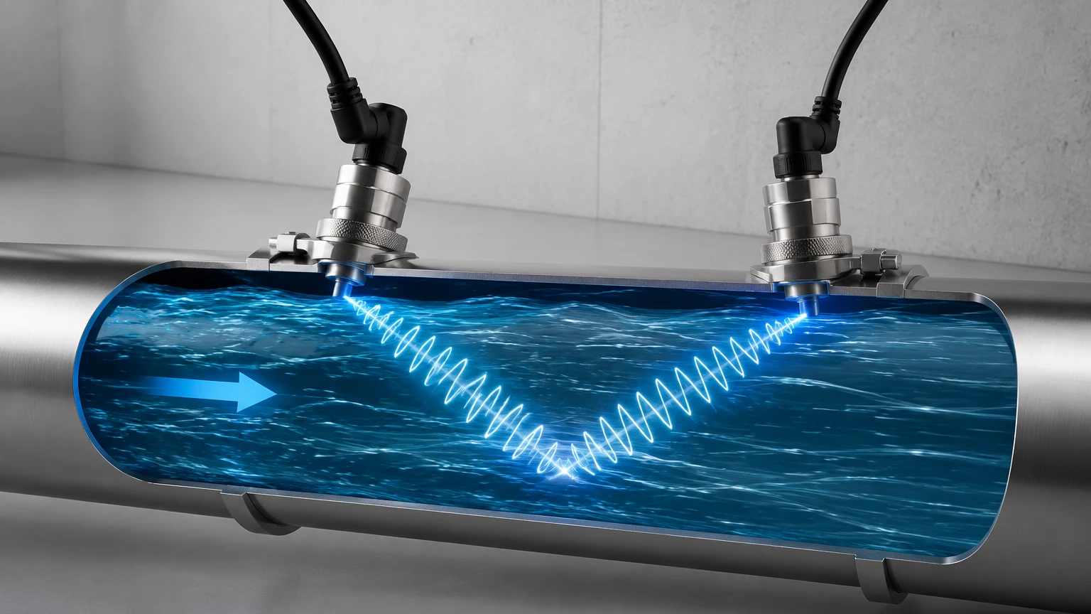
The transit-time method is the most common ultrasonic flow meter working principle used in industrial environments, particularly for clean liquids. This technology relies on the fact that sound waves traveling in the direction of fluid flow move faster than waves traveling against the flow.
The Measurement Mechanism
1. Transducer Arrangement: Two transducers (A and B) are mounted on the pipe, either opposite each other or on the same side. They function as both transmitters and receivers.
2. Downstream Signal: Transducer A sends an ultrasonic pulse to Transducer B. Because the pulse is moving with the flow, its speed is boosted by the fluid velocity.
3. Upstream Signal: Transducer B then sends a pulse back to Transducer A. This pulse must fight against the current, resulting in a slower transit time.
4. Time Difference ($Δt$): The flow meter’s electronics measure the precise time difference between these two signals. This difference is directly proportional to the velocity of the fluid within the pipe.
Mathematically, if the distance between transducers is known and the speed of sound in the static fluid is accounted for, the meter can calculate the average velocity. When combined with the cross-sectional area of the pipe, the volumetric flow rate is determined. This method is highly accurate (often within ±0.5% to ±1% of flow rate) but requires the fluid to be relatively free of solids and bubbles, which can scatter the signal.
Doppler Effect Ultrasonic Flow Meter Working Principle
While transit-time meters require clean fluids, the Doppler Effect principle is designed for "dirty" or aerated liquids. This method is named after Christian Doppler, who discovered that the frequency of a wave changes relative to an observer if the source of the wave is moving.
The Measurement Mechanism
1. Signal Transmission: A single transducer (or a pair) transmits a continuous ultrasonic beam into the pipe at a known frequency.
2. Reflection: The sound waves encounter "discontinuities" in the fluid—such as suspended solids, grit, or entrained gas bubbles. These particles act as moving reflectors.
3. Frequency Shift: The sound reflects off these moving particles and returns to the receiver. Because the particles are moving with the fluid, the frequency of the reflected signal is shifted (higher if moving toward the receiver, lower if moving away).
4. Velocity Calculation: The flow meter measures this frequency shift ($Δf$). The magnitude of the shift is directly proportional to the velocity of the reflecting particles, which represents the velocity of the fluid.
Doppler meters are ideal for wastewater, slurries, and aerated chemicals. However, they are generally less accurate than transit-time meters because they measure the velocity of the particles rather than the average velocity of the entire fluid profile.
Key Selection Criteria: Transit-Time vs. Doppler
Choosing the right ultrasonic flow meter working principle depends heavily on the fluid characteristics. The following table provides a comparison for engineering selection:
| Feature | Transit-Time Meter | Doppler Effect Meter |
| :— | :— | :— |
| Primary Fluid Type | Clean liquids (water, oils, chemicals) | Dirty/Aerated liquids (sewage, slurries) |
| Suspended Solids | < 2% by volume | > 100 ppm (parts per million) |
| Bubbles | Minimal (can cause signal loss) | Required for reflection |
| Accuracy | High (±0.5% to ±2%) | Moderate (±2% to ±5%) |
| Pipe Material | Most metals and plastics | Most metals and plastics |
| Installation Type | Inline or Clamp-on | Inline or Clamp-on |
Practical Installation Considerations
Even the most advanced ultrasonic flow meter will fail to provide accurate data if installed incorrectly. Because these meters calculate flow based on velocity profiles, the state of the fluid at the point of measurement is critical.
1. Straight Pipe Requirements
To ensure a stable, laminar flow profile, ultrasonic meters require a specific length of straight pipe before (upstream) and after (downstream) the sensor.
* Upstream: Typically 10 to 20 pipe diameters (10D – 20D).
* Downstream: Typically 5 pipe diameters (5D).
If the meter is placed too close to a pump, valve, or elbow, the resulting turbulence will cause the ultrasonic signal to fluctuate, leading to inaccurate readings.
2. Transducer Mounting (Clamp-on vs. Inline)
* Clamp-on: Transducers are strapped to the outside of the pipe. This is non-intrusive, meaning there is no need to shut down the process or cut the pipe. It is essential to use a couplant (ultrasonic grease or gel) between the transducer and the pipe surface to eliminate air gaps.
* Inline (Wetted): Transducers are built into a pipe spool piece and are in direct contact with the fluid. This often provides higher accuracy as the signal does not have to pass through the pipe wall.
3. Pipe Orientation
Horizontal pipes should have transducers mounted at the 3 o'clock and 9 o'clock positions. Mounting them at the top (12 o'clock) can result in signal loss due to air pockets, while mounting at the bottom (6 o'clock) can result in signal interference from sediment buildup.
Limitations and Technical Challenges
Despite their versatility, ultrasonic flow meters have specific limitations that engineers must manage:
* Signal Attenuation: Certain pipe materials, such as concrete-lined pipes or heavily corroded cast iron, can absorb or scatter ultrasonic signals, making clamp-on measurement difficult.
* Temperature Extremes: High temperatures can affect the speed of sound in the fluid and the integrity of the transducer couplant. High-temperature transducers are required for processes exceeding 120°C (248°F).
* Fluid Homogeneity: For transit-time meters, if the fluid is not thermally or chemically homogeneous, the speed of sound may vary across the pipe cross-section, inducing errors.
* Minimum Velocity: Most ultrasonic meters have a "low-flow cutoff." If the velocity is below approximately 0.1 m/s (0.3 fps), the time difference or frequency shift may be too small for the electronics to distinguish from background noise.
Integration with Level Measurement Systems
In many industrial setups, flow measurement is closely linked to level measurement. For example, in open channel flow (such as flumes and weirs), an ultrasonic level sensor—like those manufactured by Welk—is used to measure the height of the liquid. This height is then converted into a flow rate using standard hydraulic formulas.
While the ultrasonic flow meter working principle discussed here focuses on closed-pipe systems, the underlying technology of using acoustic pulses to determine distance or velocity remains a cornerstone of industrial automation. For professionals managing complex tank farms or chemical processing plants, reviewing the full range of ultrasonic, radar, and hydrostatic sensors on the Main Page is recommended to ensure system-wide compatibility.
Frequently Asked Questions (FAQ)
Q: Can ultrasonic flow meters measure gas flow?
A: Yes, but gas measurement requires specialized high-power transducers because gases are much less dense than liquids, leading to significant signal attenuation. Transit-time is the standard principle for gas flow.
Q: Does pipe wall thickness affect the measurement?
A: Yes, for clamp-on meters. The thickness and material of the pipe must be programmed into the flow computer so it can accurately calculate the refraction angle of the sound wave as it passes through the pipe wall into the fluid.
Q: How often does an ultrasonic flow meter need calibration?
A: Since there are no moving parts to wear out, ultrasonic meters are very stable. However, in critical applications, a yearly verification or calibration check is recommended to ensure the transducers haven't shifted and the couplant hasn't dried out.
Q: Can it measure flow in both directions?
A: Yes, transit-time ultrasonic flow meters are inherently bi-directional. They can distinguish between positive and negative time differences, allowing them to report both the direction and the rate of flow.
Conclusion
The ultrasonic flow meter working principle offers a sophisticated, non-intrusive method for monitoring industrial processes. By selecting between transit-time and Doppler technologies based on fluid clarity and understanding the critical nature of installation geometry, operators can achieve high-precision measurement with minimal maintenance. As industrial automation continues to evolve, the integration of these flow meters with advanced level measurement instruments ensures a comprehensive approach to fluid management and process efficiency.