How Are Wave Heights Measured
How Are Wave Heights Measured
In both oceanographic research and industrial process control, the ability to accurately quantify surface agitation is vital for safety, structural integrity, and operational efficiency. Whether monitoring the open sea for maritime navigation or managing the turbulent surface of a large-scale chemical reactor, the question of how are wave heights measured involves a sophisticated blend of physics, signal processing, and robust instrumentation.
Wave height is typically defined as the vertical distance between the crest (the highest point of a wave) and the adjacent trough (the lowest point). In engineering contexts, this is often expressed as "Significant Wave Height" ($H_s$), which represents the average height of the highest one-third of waves in a given sampling period. For industrial operators, understanding these dynamics is essential for protecting offshore assets, optimizing water treatment aeration, and ensuring the accuracy of level measurements in agitated vessels.
Understanding Wave Height Measurement Principles
To understand how are wave heights measured, one must first distinguish between the various physical principles employed by modern sensors. These methods generally fall into two categories: non-contact sensing and contact-based sensing.
Time-of-Flight (ToF) Principle
Most modern electronic wave measurement devices, such as radar and ultrasonic sensors, utilize the Time-of-Flight principle. The sensor emits a pulse of energy (either electromagnetic or acoustic) toward the water surface. This pulse reflects off the surface and returns to the receiver. By measuring the precise time interval between emission and reception, and knowing the constant speed of the wave (the speed of light for radar or the speed of sound for ultrasonic), the distance to the surface can be calculated. To measure wave height specifically, the sensor must take these readings at a high frequency—often 10 to 30 times per second—to capture the rapid rise and fall of the surface.
Hydrostatic Pressure Principle
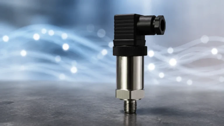
Hydrostatic sensors are submerged at a fixed depth. They measure the weight of the water column above them. As a wave passes over the sensor, the height of the water column increases at the crest and decreases at the trough, causing a corresponding change in pressure. While effective, this method requires complex algorithms to account for the "pressure attenuation" effect, where wave-induced pressure changes diminish as depth increases.
Acceleration and Buoyancy
In deep-sea oceanography, wave buoys are the standard. These devices use accelerometers to measure the vertical movement of the buoy as it rides the waves. By integrating the acceleration data twice over time, the displacement (height) can be determined. While highly accurate for open ocean swell, these are rarely used in industrial process environments due to their size and the requirement for free-floating movement.
Radar Technology for Dynamic Surface Measurement
Radar (Radio Detection and Ranging) has emerged as the premier technology for industrial wave height measurement, particularly in the oil and gas and maritime sectors. When considering how are wave heights measured in high-stakes environments, radar offers several distinct advantages over other technologies.
Frequency Modulated Continuous Wave (FMCW)
Modern radar level meters, such as those featured on the Welk Main Page, often utilize FMCW technology. Unlike simple pulse radar, FMCW transmits a continuous signal with a constantly changing frequency. The difference in frequency between the transmitted and received signal is proportional to the distance. This allows for extremely high resolution and the ability to track rapidly moving surfaces with millimeter precision.
80GHz vs. 26GHz Radar
The frequency of the radar signal significantly impacts its performance. 80GHz radar instruments provide a narrower beam angle (often as small as 3 degrees), which is critical when measuring waves near pier legs, platform supports, or within narrow stilling wells. A narrower beam minimizes "false echoes" from structural elements, ensuring that the returned signal is purely from the water surface. 26GHz radars are more common in general level applications but may struggle with the fine-grained surface detail required for accurate wave height analysis.
Sampling Rates and Data Processing
To capture a wave profile, the radar must have a high sampling rate. If a wave has a period of 5 seconds, a sensor sampling once per second will only capture five points, which is insufficient to accurately define the crest and trough. Industrial-grade wave radars typically sample at 10Hz or higher. The internal processor then applies Fast Fourier Transform (FFT) algorithms to convert the raw distance data into a wave spectrum, providing metrics like maximum wave height ($H_{max}$) and peak period ($T_p$).
Ultrasonic Sensors: Applications and Limitations
Ultrasonic sensors are a cost-effective alternative for measuring wave heights in less demanding environments, such as inland waterways, irrigation channels, and small industrial tanks.
How Ultrasonic Waves Work
Ultrasonic transducers emit high-frequency sound pulses (typically between 20kHz and 200kHz). These pulses bounce off the water surface and return to the sensor. Because sound travels much slower than light, the electronics required for timing are less complex, making these sensors more affordable.
Environmental Sensitivities
When evaluating how are wave heights measured with ultrasonic technology, one must account for the medium: air. The speed of sound is highly dependent on air temperature, humidity, and wind.
1. Temperature: Most professional ultrasonic sensors include an integrated temperature probe to compensate for changes in sound speed. However, if there is a temperature gradient between the sensor and the water, errors can occur.
2. Wind: Strong winds can "blow" the sound pulse away from the receiver or cause turbulence in the air that scatters the signal. This makes ultrasonic sensors less reliable for offshore or high-wind coastal applications.
3. Foam: Heavy foam on the surface of the water (often found in wastewater treatment or during heavy storms) absorbs sound energy rather than reflecting it, leading to signal loss.
Hydrostatic Pressure and Submerged Sensing
For applications where mounting a sensor above the water is impractical—such as under ice or in areas with heavy boat traffic—hydrostatic transmitters provide a viable solution for determining how are wave heights measured from below.
The Pressure-to-Height Relationship
The fundamental equation for hydrostatic measurement is $P = \rho gh$, where $P$ is pressure, $\rho$ is the fluid density, $g$ is gravity, and $h$ is the height of the liquid. In a wave environment, the sensor measures a dynamic pressure ($P_{total} = P_{static} + P_{dynamic}$).
Limitations of Submerged Sensors
- Depth Attenuation: The circular motion of water particles in a wave decreases exponentially with depth. If a pressure sensor is placed too deep, it will not "feel" the short-period waves at the surface. Generally, a pressure sensor can only detect waves with a wavelength at least twice the depth of the sensor.
- Fouling: Submerged sensors are prone to biofouling (growth of algae or barnacles) and siltation, which can clog the pressure diaphragm and lead to drift over time.
- Density Variations: Changes in salinity (in estuaries) or temperature affect water density, which must be compensated for to maintain accuracy.

Selection Criteria for Wave Measurement Instruments
Choosing the right technology depends on the specific requirements of the installation. The following table provides a comparison for engineering selection.
| Feature | Radar (FMCW) | Ultrasonic | Hydrostatic Pressure |
| :— | :— | :— | :— |
| Measurement Type | Non-contact | Non-contact | Contact (Submerged) |
| Accuracy | Excellent (±2mm) | Good (±0.25% of range) | Moderate (±0.1% to 0.5%) |
| Sampling Rate | High (Up to 100Hz) | Moderate (1-10Hz) | High (Continuous analog) |
| Wind/Temp Influence | None | Significant | None |
| Installation | Above surface | Above surface | Submerged |
| Maintenance | Very Low | Low | Moderate (Cleaning required) |
| Typical Use Case | Offshore platforms, sea state | Canals, tanks, calm water | Ports, tide gauges, reservoirs |
When selecting a device, engineers should prioritize the Main Page of the manufacturer's technical documentation to ensure the sampling rate and beam angle are appropriate for the expected wave frequency and amplitude.
Installation Best Practices for Accurate Wave Data
Even the most advanced sensor will provide poor data if installed incorrectly. When implementing a system to address how are wave heights measured, follow these industrial guidelines:
1. Mounting Geometry
Sensors must be mounted perfectly vertical. If a radar or ultrasonic sensor is tilted, the energy reflects away from the receiver, resulting in a weak signal. For wave measurement, the sensor should be positioned over a representative area of the water, away from walls or pillars that might cause wave reflection or diffraction (clutter).
2. Beam Clearance
Ensure the "footprint" of the sensor's beam is clear of obstructions. For a radar with a 10-degree beam angle, the footprint diameter at 10 meters is approximately 1.7 meters. Any ladders, pipes, or structural beams within this cone will create interference.
3. Stilling Wells
In some industrial applications, such as large storage tanks with heavy agitation, a stilling well (a vertical pipe with holes) is used to dampen the waves so a stable level can be measured. However, if the goal is to measure the *actual* wave height, a stilling well should be avoided or specifically designed with large enough intake ports to allow the wave frequency to pass through without significant attenuation.
4. Data Averaging and Sampling
To distinguish between a rogue wave and the average sea state, the controller or PLC (Programmable Logic Controller) must be programmed to handle large datasets. Standard level measurement involves heavy damping (averaging over minutes). Wave measurement requires the opposite: raw data must be captured quickly, and statistical analysis (like calculating the Root Mean Square or RMS) must be performed on the backend.
Limitations and Environmental Challenges
While modern technology has simplified how are wave heights measured, certain physical limitations remain:
- Surface Slope: If a wave is extremely steep, the radar or ultrasonic signal may reflect at such an angle that it does not return to the sensor. This is known as "specular reflection" and can lead to intermittent data loss during heavy storms.
- Heavy Rain and Fog: While radar is largely unaffected by atmospheric conditions, extremely heavy tropical downpours can attenuate high-frequency (80GHz) signals. Ultrasonic sensors are even more susceptible to signal scattering in these conditions.
- Power Consumption: High-frequency sampling requires significant power. For remote solar-powered installations (e.g., coastal monitoring buoys), a balance must be struck between sampling frequency and battery life.
Frequently Asked Questions (FAQ)
Q: Can a standard level transmitter be used to measure wave height?
A: Only if it has a high enough sampling rate and the output damping is turned off. Most standard level transmitters are designed to ignore waves to provide a steady reading. For wave height, you need a specialized "fast" version of the sensor.
Q: What is the difference between wave height and wave period?
A: Wave height is the vertical distance (amplitude), while wave period is the time it takes for two successive crests to pass a fixed point. Measuring both is necessary to understand the energy of the water surface.
Q: How does water salinity affect radar measurement?
A: It doesn't. Radar measures the dielectric constant change at the surface. Whether the water is fresh or salt, the reflection is strong enough for an accurate reading. Salinity only affects hydrostatic (pressure) sensors due to the change in water density.
Q: Is 80GHz radar always better than 26GHz for waves?
A: Generally, yes. The smaller wavelength and narrower beam of 80GHz radar allow it to see the "texture" of the water better and avoid interference from nearby structures, which is common in industrial settings.
For engineers and project managers tasked with monitoring fluid dynamics, understanding how are wave heights measured is the first step toward selecting a robust solution. By leveraging high-frequency radar or specialized ultrasonic sensors, facilities can gain real-time insights into surface conditions, ensuring both safety and process precision. For further technical specifications and product comparisons, visiting the Main Page of an established manufacturer like Welk provides the necessary data to make an informed procurement decision.