Ultrasonic Gas Flow Meter Working Principle
Ultrasonic Gas Flow Meter Working Principle
In the landscape of industrial process control, the accurate measurement of gas flow is a fundamental requirement for efficiency, safety, and fiscal accounting. Among the various technologies available, ultrasonic flow meters have emerged as a preferred solution for complex gas applications due to their non-intrusive nature and high precision. Understanding the ultrasonic gas flow meter working principle is essential for engineers and plant managers who must select the right instrumentation for demanding environments such as chemical processing, natural gas distribution, and industrial automation.
As a professional manufacturer of industrial measurement instruments, Welk provides a comprehensive range of solutions, including radar level meters and ultrasonic sensors. For those seeking detailed product specifications and application support across the broader spectrum of level and flow measurement, visiting the Main Page offers a deep dive into available hardware and engineering services.
The Core Ultrasonic Gas Flow Meter Working Principle
At its most fundamental level, an ultrasonic gas flow meter operates by utilizing sound waves to determine the velocity of a gas flowing through a pipe. Unlike mechanical meters that rely on moving parts—which are prone to wear and pressure drops—ultrasonic meters use electronic transducers to send and receive acoustic signals. There are two primary methods used in this technology: Transit-Time (Time-of-Flight) and the Doppler Effect. In the context of gas measurement, the Transit-Time method is the industry standard.
The Transit-Time Method
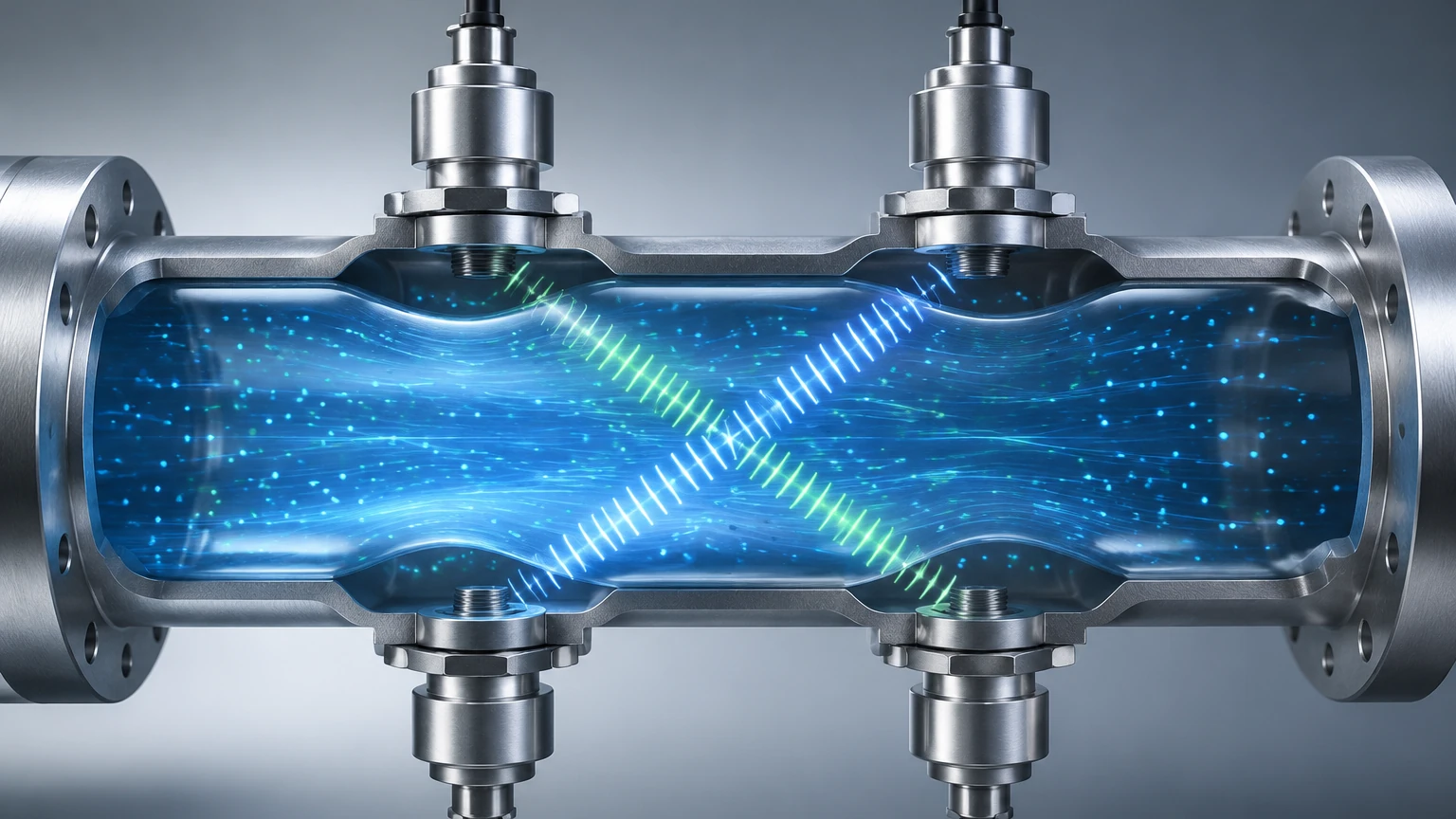
The transit-time ultrasonic gas flow meter working principle relies on the difference in the time it takes for an ultrasonic pulse to travel between two transducers. These transducers are typically mounted at an angle to the pipe's axis, facing each other. One transducer acts as a transmitter (upstream), while the other acts as a receiver (downstream), and then they switch roles.
1. Downstream Transmission: When a pulse is sent from the upstream transducer to the downstream transducer, it travels with the flow of the gas. This "tailwind" effect causes the sound wave to travel faster.
2. Upstream Transmission: Conversely, when a pulse is sent from the downstream transducer to the upstream transducer, it travels against the flow. This "headwind" effect slows the sound wave down.
3. Time Difference (Delta T): The flow meter’s electronics measure the time for both paths with nanosecond precision. The difference between these two travel times is directly proportional to the velocity of the gas.
The mathematical relationship can be simplified as follows:
If $t_{up}$ is the time taken to travel upstream and $t_{down}$ is the time taken to travel downstream, the gas velocity ($v$) is calculated based on the distance between transducers ($L$) and the angle of the path ($ heta$):
$$v = \frac{L}{2 \cos \theta} \left( \frac{1}{t_{down}} – \frac{1}{t_{up}} \right)$$
Once the velocity is determined, the meter calculates the volumetric flow rate by multiplying the velocity by the cross-sectional area of the pipe.
The Role of the Speed of Sound (SoS)
An interesting byproduct of the transit-time ultrasonic gas flow meter working principle is the calculation of the Speed of Sound (SoS) in the medium. By averaging the upstream and downstream travel times, the meter can determine the SoS of the gas. This is a powerful diagnostic tool. Since the SoS is dependent on gas composition, temperature, and pressure, any significant deviation from expected values can alert operators to changes in gas quality or potential sensor fouling.
Key Components of an Ultrasonic Gas Flow System
To implement the ultrasonic gas flow meter working principle effectively, several critical components must work in harmony:
* Transducers: These are typically piezoelectric crystals that convert electrical energy into mechanical vibrations (ultrasonic pulses) and vice versa. In gas applications, transducers must be designed to overcome the high acoustic impedance mismatch between the solid transducer face and the low-density gas.
* Signal Processing Unit (Transmitter): This is the "brain" of the meter. It controls the timing of the pulses, filters out ambient noise, and performs the complex calculations required to output flow data.
* Flow Cell or Spool Piece: For high-accuracy applications, the transducers are pre-mounted in a calibrated section of pipe known as a spool piece. This ensures the geometry is fixed and the path length is precisely known.
Multi-Path Configurations
While a single-path (two transducers) meter is sufficient for some applications, industrial-grade gas flow meters often use multi-path configurations. By sending pulses across multiple chords of the pipe (e.g., 2-path, 4-path, or even 8-path systems), the meter can account for non-ideal flow profiles, such as swirl or turbulence caused by upstream elbows or valves. Multi-path meters provide much higher accuracy and redundancy, which is critical for custody transfer in the oil and gas sector.
Practical Selection Criteria
When evaluating gas flow measurement technology, engineers must consider the specific constraints of their process. The following table outlines typical performance characteristics for ultrasonic gas flow meters compared to other common technologies.
| Feature | Ultrasonic (Transit-Time) | Thermal Mass Flow | Vortex Shedding |
| :— | :— | :— | :— |
| Medium | Clean/Dry Gases | Clean Gases | Steam, Gas, Liquids |
| Accuracy | ±0.5% to ±1.0% | ±1.0% | ±1.0% to ±1.5% |
| Turndown Ratio | 100:1 | 50:1 | 20:1 |
| Pressure Drop | Negligible | Low | Moderate |
| Moving Parts | None | None | None |
| Maintenance | Low | Moderate (Sensor cleaning) | Low |
When to Choose Ultrasonic Technology
Ultrasonic meters are ideal when the following conditions are met:
* High Turndown Requirements: They can measure very low velocities (0.1 m/s) and very high velocities (up to 30 m/s or more).
* Zero Pressure Drop: Because there are no obstructions in the flow path, they are highly energy-efficient.
* Large Pipe Diameters: They are cost-effective for large pipes (DN200 to DN3000) where other technologies become prohibitively expensive or heavy.
Installation Considerations
To ensure the ultrasonic gas flow meter working principle is applied accurately, proper installation is paramount. Acoustic signals are sensitive to the environment within the pipe.
1. Straight Pipe Runs: To achieve a stable flow profile, a minimum of 10D (ten times the pipe diameter) of straight pipe upstream and 5D downstream is generally recommended. If space is limited, flow conditioners may be required.
2. Orientation: For gas applications, transducers are often mounted in the horizontal plane (3 o'clock and 9 o'clock positions) to prevent the accumulation of moisture or debris on the transducer faces, which could attenuate the signal.
3. Pressure and Temperature: Gas density changes significantly with pressure and temperature. Most industrial ultrasonic gas flow systems include integrated Pressure (P) and Temperature (T) sensors to convert measured "actual" flow to "standard" or "normal" flow (e.g., Nm³/h).
4. Acoustic Noise: High-frequency noise from control valves or pressure regulators can interfere with the ultrasonic pulses. Meters should be installed away from such noise sources, or acoustic filters should be used.
Limitations and Challenges
Despite their versatility, ultrasonic gas flow meters have limitations that must be acknowledged:
* Gas Attenuation: Certain gases, such as Carbon Dioxide (CO2), absorb ultrasonic energy more than others. This can weaken the signal, requiring higher-power transducers or lower frequencies.
* Minimum Pressure: Ultrasonic signals travel poorly through very low-pressure gas (vacuum or near-atmospheric). Most transit-time gas meters require a minimum operating pressure (e.g., >1 bar) to ensure reliable signal transmission.
* Contamination: While they handle dry gas exceptionally well, heavy moisture or liquid droplets can scatter the ultrasonic beam, leading to signal loss.
Integration with Industrial Automation
In modern industrial facilities, flow data is rarely used in isolation. It is typically integrated into a broader automation architecture. Welk’s expertise in level measurement instruments, such as hydrostatic transmitters and magnetic gauges, complements flow data to provide a full picture of tank inventory and process throughput. By combining accurate level data with precise gas flow measurement, plants can achieve a more rigorous mass balance, improving both safety and profitability.
Frequently Asked Questions (FAQ)
1. Can ultrasonic gas flow meters measure wet gas?
Standard transit-time meters are designed for dry gas. If the gas contains significant liquid (wet gas), the liquid droplets can scatter the ultrasonic signal. Specialized "wet gas" ultrasonic meters exist, but they use different processing algorithms and transducer configurations.
2. How does gas composition affect the measurement?
The transit-time ultrasonic gas flow meter working principle is largely independent of gas composition because it measures the *difference* in time. However, the Speed of Sound calculation *is* affected. If the gas composition changes drastically, the meter must be able to handle the resulting change in signal attenuation.
3. Do these meters require periodic calibration?
While they have no moving parts to wear out, periodic verification is recommended. Many high-end meters offer "self-diagnostics" that check signal strength and SoS, which can extend calibration intervals. For custody transfer, annual or bi-annual flow lab calibration is often a regulatory requirement.
4. What is the difference between a clamp-on and an inline gas meter?
Clamp-on meters are attached to the outside of the pipe, making them ideal for retrofitting without cutting the pipe. Inline meters (spool pieces) have transducers in direct contact with the gas. For gas measurement, inline meters are generally preferred because the signal does not have to penetrate the pipe wall, which is difficult for ultrasound in a gas medium.
5. What is the maximum temperature these meters can handle?
Standard transducers can typically handle up to 150°C (302°F). High-temperature versions with specialized cooling or buffer rods can extend this range to over 400°C (752°F) for specific industrial applications.
Conclusion
The ultrasonic gas flow meter working principle represents a pinnacle of non-mechanical measurement technology. By leveraging the speed of sound and precision electronics, these meters provide reliable data in some of the most challenging industrial environments. Whether managing natural gas pipelines or optimizing chemical reactors, understanding the physics and practical requirements of these instruments ensures long-term operational success. For further information on integrating flow and level measurement into your facility, explore the resources available on the Welk Main Page.
Download Ultrasonic Gas Flow Meter Working Principle as a PDF