Ultrasonic Gas Flow Meter
Ultrasonic Gas Flow Meter
Ultrasonic gas flow meters have become a cornerstone of modern industrial process control and custody transfer. Unlike traditional mechanical meters that rely on moving parts, an ultrasonic gas flow meter utilizes acoustic signals to determine the velocity of a gas moving through a pipe. This non-intrusive approach offers significant advantages in terms of maintenance, pressure drop, and long-term reliability. In complex industrial environments—ranging from natural gas distribution to chemical processing—selecting the right flow measurement technology is as critical as choosing the correct level measurement instrumentation for storage tanks.
Measurement Principles of Ultrasonic Gas Flow Meters
To understand the application of an ultrasonic gas flow meter, one must first grasp the underlying physics of acoustic wave propagation in a moving medium. There are two primary methods used in ultrasonic flow measurement: Transit-Time and Doppler Effect. For gas applications, the transit-time method is almost exclusively used due to the low density and high purity of most industrial gases.
The Transit-Time Principle
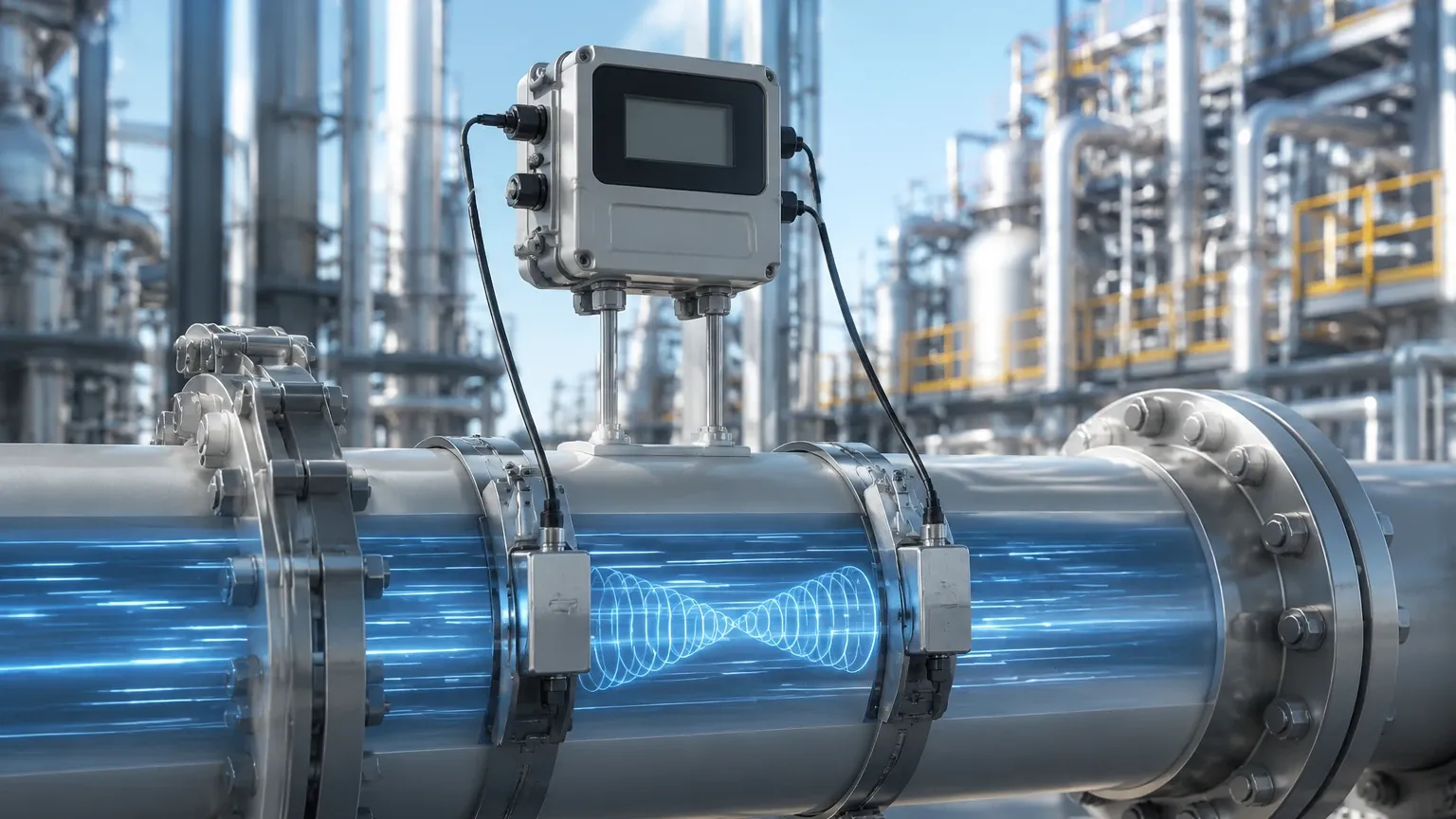
The transit-time method operates on the principle that the time it takes for an ultrasonic pulse to travel between two transducers depends on the velocity of the gas. Two transducers are mounted on the pipe, typically at an angle to the flow. One acts as a transmitter and the other as a receiver, and then they switch roles.
1. Upstream to Downstream: When the pulse travels in the direction of the flow, its speed is increased by the gas velocity.
2. Downstream to Upstream: When the pulse travels against the flow, its speed is decreased.
By measuring the precise time difference (often in nanoseconds) between these two signals, the meter calculates the flow velocity. The formula used is generally expressed as:
$$v = \frac{L}{2 \cos \theta} \left( \frac{1}{t_{up}} – \frac{1}{t_{down}} \right)$$
Where:
* $v$ is the flow velocity.
* $L$ is the acoustic path length.
* $\theta$ is the angle of the transducers relative to the flow.
* $t_{up}$ and $t_{down}$ are the transit times.
The Role of Sound Speed
In addition to velocity, the meter calculates the speed of sound in the gas. This is a critical diagnostic tool. If the measured speed of sound deviates from the theoretical speed of sound (based on gas composition, pressure, and temperature), it may indicate a change in gas quality or a build-up of contaminants on the transducers.
Key Evaluation Criteria for Selection
Selecting an ultrasonic gas flow meter requires a detailed analysis of the process conditions. Unlike liquid measurement, gas measurement is highly sensitive to pressure and temperature variations. Engineers should evaluate the following criteria before procurement:
1. Gas Composition and Attenuation
Not all gases transmit sound equally. Gases with high CO2 content or very low density (like hydrogen at low pressure) can attenuate ultrasonic signals significantly. It is essential to confirm that the meter’s transducers are capable of penetrating the specific gas medium at the intended operating pressure.
2. Pressure and Temperature Ranges
Ultrasonic signals require a medium to travel through. At very low pressures (near vacuum), there are fewer molecules to carry the sound wave, which can lead to signal loss. Conversely, high-pressure applications are ideal for ultrasonic meters as the signal-to-noise ratio improves. Standard industrial models typically handle temperatures from -40°C to +150°C, though specialized high-temperature versions exist.
3. Turndown Ratio and Accuracy
One of the greatest strengths of the ultrasonic gas flow meter is its wide turndown ratio, often reaching 100:1 or higher. This allows the meter to capture both low-flow leakage and peak demand accurately. For custody transfer, accuracies of ±0.5% or better are common, while process-grade meters may range from ±1.0% to ±2.0%.
Technical Selection Table
| Parameter | Requirement/Specification | Impact on Performance |
| :— | :— | :— |
| Pipe Size | 50 mm to 1000 mm (2" to 40") | Larger pipes often require multi-path configurations for accuracy. |
| Gas Pressure | Minimum 1 bar (abs); Max up to 250 bar | Low pressure increases signal attenuation. |
| Flow Profile | Fully developed laminar or turbulent flow | Disturbed profiles require longer straight runs or flow conditioners. |
| Accuracy | ±0.5% (Custody) to ±2.0% (Process) | Higher accuracy requires multi-path (3-8 paths) meters. |
| Power Supply | 24V DC or Loop-powered | Loop-powered units are limited in signal processing power. |
| Output | 4-20mA, Modbus RTU, HART, Pulse | Integration with PLC/SCADA systems for real-time monitoring. |
Installation Considerations and Best Practices
Proper installation is the most critical factor in ensuring the long-term accuracy of an ultrasonic gas flow meter. Because these meters calculate flow based on the velocity profile within the pipe, any turbulence can introduce significant errors.
Straight Pipe Runs
To ensure a stable flow profile, manufacturers generally recommend a minimum of 10 diameters (10D) of straight pipe upstream of the meter and 5 diameters (5D) downstream. If the installation site involves multiple elbows, valves, or reducers, these requirements may increase to 20D or more. In space-constrained environments, a flow conditioner (a perforated plate or vane) can be installed to artificially stabilize the flow.
Orientation and Positioning
For gas applications, the transducers should ideally be mounted in the horizontal plane (3 o'clock and 9 o'clock positions). This prevents moisture or condensate from settling on the bottom transducer and prevents gas bubbles or debris from accumulating on the top transducer, both of which would interfere with the acoustic signal.
Acoustic Noise Interference
Ultrasonic gas flow meters can be sensitive to "ultrasonic noise" generated by nearby pressure-regulating valves. These valves can create high-frequency noise that overlaps with the meter’s operating frequency. Installing the meter a significant distance away from such valves or using acoustic filters is necessary in high-pressure drop applications.
Comparison with Other Flow Technologies
When evaluating an ultrasonic gas flow meter, it is helpful to compare it against traditional technologies like Orifice Plates or Thermal Mass Flow Meters.
* Orifice Plates: These create a significant pressure drop and have a limited turndown ratio (typically 4:1). They also require frequent inspection for edge wear. The ultrasonic meter has zero pressure drop and no moving parts to wear out.
* Thermal Mass Flow Meters: While excellent for low-flow detection, thermal meters are highly dependent on knowing the exact thermal properties of the gas. If the gas composition changes, the calibration becomes invalid. Ultrasonic meters are less sensitive to minor composition changes because they measure velocity directly.
* Vortex Meters: These are robust but require a minimum flow velocity to "shed" vortices. They also introduce a slight pressure drop and can be sensitive to pipe vibration, whereas ultrasonic meters are largely immune to mechanical vibration.
For engineers looking to integrate these flow solutions into a broader plant automation strategy, including level monitoring and tank management, reviewing comprehensive product options and application support on the Main Page is recommended to ensure all instrumentation is compatible and optimized for the specific industrial environment.
Limitations and Common Risks
Despite their versatility, ultrasonic gas flow meters are not a universal solution for every gas application. Understanding their limitations is key to avoiding project failure.
1. Minimum Pressure Requirements: As mentioned, these meters struggle in near-atmospheric or vacuum conditions. If the gas density is too low, the transducers cannot effectively couple the sound energy into the gas.
2. Liquid Entrainment: While ultrasonic meters can handle some moisture, "wet gas" (gas with high liquid content) can cause signal scattering. If liquid droplets coat the transducer faces, the signal may be lost entirely.
3. Initial Cost: The capital expenditure for a high-quality, multi-path ultrasonic gas flow meter is significantly higher than for an orifice plate or a vortex meter. However, the total cost of ownership (TCO) is often lower due to reduced maintenance and energy savings from zero pressure drop.
4. Signal Processing Complexity: These meters rely on sophisticated electronics. In environments with extreme electromagnetic interference (EMI), the signal processing unit must be properly shielded and grounded to prevent data corruption.
Frequently Asked Questions (FAQs)
Q: Can an ultrasonic gas flow meter measure bi-directional flow?
A: Yes. One of the inherent advantages of the transit-time principle is that it naturally measures flow in both directions. This makes it ideal for applications like gas storage injection and withdrawal.
Q: How often do the transducers need to be calibrated?
A: Because there are no moving parts to wear, the physical geometry of the meter does not change. However, the electronics should be checked annually, and for custody transfer applications, a flow lab recalibration may be required every 3 to 5 years depending on local regulations.
Q: Is it possible to install an ultrasonic meter without cutting the pipe?
A: Yes, there are "clamp-on" ultrasonic gas flow meters. While convenient, they are generally less accurate than "spool-piece" (in-line) meters because the signal must travel through the pipe wall, which causes significant signal loss and refraction. Clamp-on models are best suited for temporary surveys or non-critical process monitoring.
Q: How does gas temperature affect the measurement?
A: Temperature affects the speed of sound and the density of the gas. While the transit-time calculation for velocity is independent of the speed of sound, the meter uses temperature data to convert "actual flow" (ACMH) to "standard flow" (SCMH) for billing and mass balance purposes.
Conclusion
The ultrasonic gas flow meter represents a high-performance solution for modern industry, offering a blend of accuracy, rangeability, and low maintenance. By understanding the transit-time principle and adhering to strict installation guidelines regarding straight pipe runs and noise mitigation, facilities can achieve highly reliable gas measurement. Whether managing natural gas pipelines or monitoring industrial process gases, the integration of these meters into a wider instrumentation network—alongside advanced level transmitters and switches—ensures optimal process efficiency and safety. Before moving forward with a project, it is essential to confirm gas composition, operating pressure, and the required accuracy class to select the most cost-effective and technically sound meter configuration.