Ultrasonic Gas Flow Sensor
Ultrasonic Gas Flow Sensor
In the landscape of industrial automation and process control, the accurate measurement of gas flow is critical for operational efficiency, safety, and fiscal accountability. Among the various technologies available, the ultrasonic gas flow sensor has emerged as a preferred solution for demanding applications ranging from natural gas custody transfer to compressed air management. This guide explores the fundamental principles, selection criteria, and practical installation requirements for ultrasonic gas flow sensors, providing engineers with the necessary context to implement these instruments effectively.
Understanding the Principles of Ultrasonic Gas Measurement
Ultrasonic gas flow sensors operate on the principle of acoustic wave propagation within a moving fluid. Unlike mechanical meters that rely on moving parts, ultrasonic sensors are solid-state devices that measure the velocity of a gas by analyzing the behavior of ultrasonic pulses as they traverse the flow stream.
Transit-Time Differential Method
The most common technology used in industrial ultrasonic gas flow sensors is the transit-time differential method. This technique utilizes a pair of transducers, typically mounted diagonally across a pipe. Each transducer functions as both a transmitter and a receiver.
1. Downstream Transmission: An ultrasonic pulse is sent from the upstream transducer to the downstream transducer. Because the pulse is traveling with the flow, its speed is increased by the velocity of the gas.
2. Upstream Transmission: A pulse is then sent from the downstream transducer to the upstream transducer. This pulse travels against the flow, and its speed is effectively reduced.
The sensor electronics measure the time of flight for both pulses ($t_{up}$ and $t_{down}$) with nanosecond precision. The difference between these two times ($Δt$) is directly proportional to the velocity of the gas. By combining this velocity with the cross-sectional area of the pipe and applying corrections for the gas's compressibility and temperature, the sensor calculates the volumetric and mass flow rates.
The Physics of Sound in Gas
Measuring gas presents unique challenges compared to liquids. The speed of sound in gas is highly dependent on the gas composition, temperature, and pressure. For instance, the speed of sound in air at 20°C is approximately 343 m/s, but this changes significantly if the medium is methane or carbon dioxide. High-quality ultrasonic gas flow sensors incorporate sophisticated algorithms to account for these variables, ensuring that the measurement remains accurate even if the gas density fluctuates.
Types of Ultrasonic Gas Flow Sensors
When selecting a sensor, engineers must choose between different mechanical configurations based on the application's accuracy requirements and installation constraints.
Inline Ultrasonic Sensors
Inline sensors consist of a dedicated pipe section (spool piece) with pre-installed transducers. These are factory-calibrated and offer the highest level of accuracy, often reaching ±0.5% to ±1% of the reading. They are commonly used in custody transfer, where high precision is required for financial transactions involving natural gas.
Clamp-on Ultrasonic Sensors
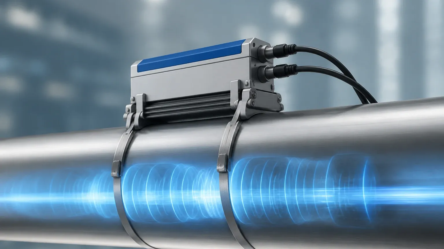
Clamp-on sensors are mounted on the exterior of an existing pipe. They transmit ultrasonic signals through the pipe wall and into the gas stream. While historically used primarily for liquids, advancements in transducer sensitivity have made clamp-on ultrasonic gas flow sensors viable for high-pressure gas lines. Their primary advantage is non-invasive installation, which eliminates the need to shut down the process or cut into the piping.
Multi-Path vs. Single-Path
To account for non-uniform flow profiles (where gas moves faster in the center of the pipe than at the walls), many industrial sensors use multiple acoustic paths. A four-path or six-path sensor provides a much more detailed map of the flow profile, significantly increasing accuracy in turbulent conditions compared to a single-path sensor.
Key Evaluation Criteria for Industrial Applications
Selecting the right ultrasonic gas flow sensor requires a thorough analysis of the process environment. Below are the primary factors that influence sensor performance.
1. Gas Composition and Density
Ultrasonic signals attenuate (lose energy) more rapidly in gases than in liquids. Low-density gases or low-pressure applications (below 5 bar / 72 psi) can sometimes struggle to maintain a strong enough signal for reliable measurement. It is essential to confirm the minimum operating pressure with the manufacturer.
2. Flow Velocity Range
Ultrasonic sensors excel at measuring a wide range of velocities, often referred to as the "turndown ratio." While mechanical meters may have a 10:1 or 20:1 turndown, ultrasonic sensors can often achieve 100:1 or better. They are capable of measuring very low flow rates (down to 0.1 m/s) and very high velocities (up to 30 or 40 m/s) without the risk of mechanical wear.
3. Temperature and Pressure Limits
Standard industrial sensors typically handle temperatures from -40°C to +150°C. For high-temperature applications, such as steam or hot exhaust gases, specialized transducers with thermal offsets are required. Similarly, the sensor housing must be rated for the maximum possible system pressure.
4. Accuracy and Calibration
Determine if the application requires "process-grade" accuracy (±2-3%) or "custody-transfer" accuracy (±0.5%). Higher accuracy sensors require multi-path configurations and rigorous laboratory calibration before deployment.
Technical Selection Table
| Feature | Inline Ultrasonic Sensor | Clamp-on Ultrasonic Sensor |
| :— | :— | :— |
| Accuracy | High (±0.5% to ±1.0%) | Moderate (±1.0% to ±3.0%) |
| Installation | Requires pipe cutting | Non-invasive (External) |
| Pressure Drop | Zero (Full bore) | Zero |
| Maintenance | Low (No moving parts) | Very Low (No contact with media) |
| Best For | Custody transfer, critical process | Retrofitting, temporary measurement |
| Pipe Size Range | 25 mm to 1000 mm+ | 50 mm to 5000 mm |
Installation Best Practices
Even the most advanced ultrasonic gas flow sensor will fail to provide accurate data if installed incorrectly. Because these sensors measure velocity, they are sensitive to disturbances in the flow profile caused by valves, elbows, or pumps.
Straight Pipe Requirements
To ensure a fully developed laminar flow profile, sensors typically require a minimum length of straight pipe upstream and downstream of the installation point.
- Upstream: Generally 10 to 20 diameters (D) of straight pipe.
- Downstream: Generally 5 diameters (D) of straight pipe.
If these distances cannot be met, a flow conditioner (a perforated plate or vane assembly) may be necessary to stabilize the gas stream.
Transducer Orientation
For horizontal pipes, transducers should ideally be mounted at the 3 o'clock and 9 o'clock positions (the sides of the pipe). This prevents signal interference from condensate or moisture pooling at the bottom of the pipe, or air bubbles/sediment collecting at the top.
Signal Interference and Noise
Ultrasonic sensors can be affected by "acoustic noise" generated by nearby pressure-reducing valves (PRVs). These valves can create high-frequency noise that overlaps with the sensor's operating frequency (typically 50 kHz to 200 kHz for gas). Placing the sensor as far as possible from such valves is a critical design consideration.
Limitations and Common Risks
While highly versatile, ultrasonic gas flow sensors are not a universal solution for every gas application.
* High Attenuation in Specific Gases: Gases like Carbon Dioxide (CO2) have high acoustic absorption properties. Measuring CO2 at low pressures often requires higher-powered transducers or lower-frequency signals.
* Moisture and Droplets: While ultrasonic sensors can handle some moisture, heavy condensation or "slugs" of liquid in the gas line can block the ultrasonic signal entirely, leading to a "signal loss" error.
* Initial Cost: The upfront investment for a high-quality ultrasonic spool piece is generally higher than that of a thermal mass meter or a vortex meter. However, the total cost of ownership is often lower due to reduced maintenance and lack of pressure drop (which saves energy costs).
Frequently Asked Questions (FAQ)
Q: Can ultrasonic gas flow sensors measure steam?
A: Yes, but it requires specialized high-temperature transducers and electronics designed to handle the high velocity and potential for condensation associated with steam flow.
Q: Do these sensors require periodic recalibration?
A: Because there are no moving parts to wear down, the physical geometry of the sensor does not change. However, in regulated industries like oil and gas, periodic electronic verification or laboratory recalibration is often mandated by local standards.
Q: Is the measurement affected by changes in gas pressure?
A: The transit-time measurement determines the *actual* velocity of the gas. To calculate *standard* or *normal* flow (mass flow), the system must integrate pressure and temperature sensors (P&T compensation).
Q: Can I use a liquid ultrasonic meter for gas?
A: No. The transducers used for liquids are designed for much higher acoustic impedances. Gas transducers must be specifically engineered to couple acoustic energy into a much less dense medium.
Conclusion
Implementing an ultrasonic gas flow sensor offers significant advantages in terms of rangeability, lack of pressure drop, and long-term reliability. By understanding the transit-time principle and adhering to strict installation guidelines regarding straight pipe runs and acoustic noise mitigation, engineers can achieve high-precision flow monitoring in the most challenging industrial environments.
For more detailed technical specifications and to explore various industrial measurement technologies, you may Review product options and application support on our Main Page. As a professional manufacturer, Welk provides customized solutions to ensure your level and flow measurement systems meet the highest standards of accuracy and durability.