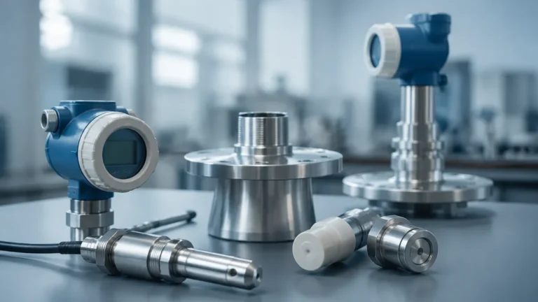
Ultrasonic Level Measurement
Ultrasonic Level Measurement
Ultrasonic level measurement has become a cornerstone technology in industrial process control, offering a non-contact, reliable, and cost-effective method for monitoring liquid and solid levels. As industries strive for higher automation and precision, understanding the engineering principles, selection criteria, and installation nuances of ultrasonic sensors is essential for plant managers and system integrators. This guide provides a technical overview of how these instruments function and how to implement them effectively in various industrial environments.
Understanding the Principle of Ultrasonic Level Measurement
The fundamental operation of ultrasonic level measurement is based on the "time-of-flight" (TOF) principle. An ultrasonic transducer, typically mounted at the top of a vessel, emits high-frequency sound pulses—well above the range of human hearing, usually between 20 kHz and 200 kHz. These sound waves travel through the air or gas space in the tank, reflect off the surface of the medium (liquid or solid), and return to the transducer.
The sensor measures the time interval between the emission of the pulse and the reception of the echo. Since the speed of sound in air is a known constant (approximately 340 meters per second at 20°C), the distance between the sensor and the material surface can be calculated using the formula:
Distance = (Speed of Sound × Time Delay) / 2
The level of the material is then determined by subtracting this measured distance from the total height of the tank (the calibration distance). Modern instruments, such as those provided by Welk, integrate advanced microprocessors to filter out false echoes and compensate for environmental variables.
The Role of Temperature Compensation
The speed of sound is significantly influenced by the temperature of the medium through which it travels. In air, the speed of sound increases by approximately 0.6 meters per second for every degree Celsius increase in temperature. To maintain accuracy, industrial ultrasonic level meters include a built-in temperature sensor to monitor the air space. The electronics automatically adjust the calculation based on real-time temperature data to ensure the measurement remains precise despite fluctuating ambient or process temperatures.
Key Components of an Ultrasonic Level System
An industrial-grade ultrasonic level measurement system consists of several critical components designed to withstand harsh environments while maintaining signal integrity:
1. Transducer (The Probe): This contains piezoelectric crystals that convert electrical energy into mechanical vibrations (sound pulses) and vice versa. The material of the transducer face (e.g., PVDF, PTFE, or UPVC) determines its chemical resistance.
2. Electronic Controller: This unit manages pulse generation, signal processing, and data output. It often includes a display for local configuration and diagnostic tools.
3. Housing: For industrial applications, housings are typically rated IP66, IP67, or IP68 to protect against dust and water ingress. In hazardous areas, explosion-proof or intrinsically safe housings are required.
4. Signal Output: Most systems provide a standard 4-20mA analog output, often with HART protocol, or digital communication options like RS485 (Modbus) for integration into PLC or SCADA systems.
Advantages and Limitations of Ultrasonic Technology
Advantages
* Non-Contact Measurement: Because the sensor does not touch the medium, it is ideal for corrosive, viscous, or abrasive fluids that would damage contact-based sensors like float switches or hydrostatic probes.
* Low Maintenance: With no moving parts to wear out or clog, ultrasonic sensors require significantly less upkeep than mechanical alternatives.
* Versatility: They can measure both liquids and bulk solids (though solids require more careful sensor selection due to uneven surfaces).
* Ease of Installation: Most units are top-mounted and can be installed without emptying the tank.
Limitations
* Vacuum and Pressure: Ultrasonic waves require a medium (air or gas) to travel. Therefore, they cannot function in a vacuum. High-pressure environments can also alter the speed of sound and affect signal strength.
* Surface Conditions: Heavy foam, extreme turbulence, or floating debris can absorb or scatter the sound waves, leading to signal loss.
* Dust and Steam: While moderate dust is manageable, very high concentrations of dust or dense steam can attenuate the ultrasonic pulse.
* Tank Geometry: Internal obstructions like ladders, agitators, or pipes can create "false echoes" if the sensor is not positioned correctly.
Selection Criteria for Industrial Applications
Choosing the right instrument for ultrasonic level measurement requires a detailed analysis of the process conditions. Engineers should consider the following factors:
* Measurement Range: Sensors are rated for specific maximum distances (e.g., 5m, 10m, 15m, or 30m). It is standard practice to select a sensor with a range slightly longer than the tank height to ensure reliability at the bottom.
* The "Dead Zone" (Blocking Distance): Every ultrasonic sensor has a minimum distance near the transducer face where it cannot measure. This is known as the dead zone. If the liquid level enters this zone, the sensor will provide an error or an incorrect reading.
* Chemical Compatibility: The transducer face must be compatible with the vapors in the tank. For acidic or alkaline environments, PVDF or PTFE-coated transducers are preferred.
* Beam Angle: This defines the width of the ultrasonic cone. A narrower beam angle is better for tall, narrow tanks or tanks with many internal obstructions.
Practical Selection Table for Ultrasonic Sensors
| Feature | Standard Liquid Sensor | Long-Range Sensor | Chemical Resistant Sensor |
| :— | :— | :— | :— |
| Typical Range | 0.3m – 8m | 0.5m – 25m | 0.25m – 12m |
| Dead Zone | 250mm – 350mm | 500mm – 800mm | 200mm – 300mm |
| Beam Angle | 8° – 12° | 5° – 8° | 10° – 12° |
| Transducer Material | ABS / Nylon | PU / Epoxy | PVDF / PTFE |
| Output | 4-20mA / HART | 4-20mA / Modbus | 4-20mA / Relay |
| Best Use Case | Water storage tanks | Large silos/reservoirs | Chemical dosing tanks |
Installation Guidelines and Best Practices
Correct installation is the most critical factor in the success of an ultrasonic level measurement application. Improper mounting is the cause of over 80% of field failures.
Positioning
* Avoid the Center: In cylindrical tanks with domed tops, do not mount the sensor in the exact center. This can cause the reflected signal to focus and create multiple echoes that confuse the electronics.
* Keep Away from Walls: Ensure the ultrasonic beam cone does not hit the tank wall. A general rule is to keep the sensor at a distance from the wall equal to at least 1/6th of the tank height.
* Avoid the Inflow: Never mount the sensor directly above the filling inlet. The falling liquid or falling solids will interfere with the sound pulse.
Mounting Orientation
* Perpendicularity: The transducer face must be perfectly parallel to the liquid surface. Even a few degrees of tilt can cause the echo to reflect away from the sensor, resulting in a "Loss of Echo" (LOE) error.
* Nozzle Length: If using a mounting nozzle or standpipe, ensure the transducer face extends slightly past the bottom of the nozzle. If the sensor is recessed too far inside a pipe, the pipe walls will create interference.
Environmental Shielding
In outdoor installations, a sunshade is recommended. Direct sunlight can heat the sensor housing significantly higher than the actual air temperature, leading to inaccurate temperature compensation and measurement errors.
Common Industrial Applications
Ultrasonic level measurement is highly versatile across multiple sectors:
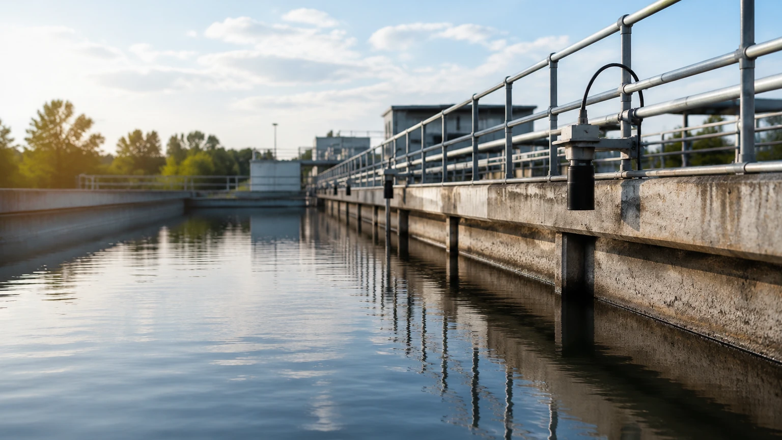
1. Water and Wastewater Treatment: Monitoring levels in wet wells, pump stations, and open channels (using flumes or weirs). It is also used for chemical tank levels (alum, bleach, polymers).
2. Chemical Processing: Used in storage tanks for acids, bases, and solvents where non-contact measurement prevents sensor corrosion.
3. Food and Beverage: Ideal for hygienic applications where the sensor must not touch the product, such as juice, milk, or sauce storage (provided there is no heavy foaming).
4. Industrial Automation: General liquid storage in manufacturing plants, including lubricants, coolants, and wastewater pits.
For a comprehensive overview of available industrial instrumentation and technical specifications, engineers can visit the Main Page to review product options and application support provided by Welk.
Troubleshooting and Maintenance
While ultrasonic sensors are low-maintenance, certain issues can arise during operation:
* Loss of Echo (LOE): This usually occurs due to heavy foam, excessive turbulence, or the material level entering the dead zone. Increasing the "Gain" or "Sensitivity" in the software settings can sometimes help, but physical changes (like adding a stilling well) may be necessary.
* Intermittent Readings: Often caused by electrical noise or poor grounding. Ensure the signal cable is shielded and kept away from high-voltage power lines.
* Build-up on Transducer: In humid or dusty environments, condensation or dust can accumulate on the transducer face. Periodic cleaning with a soft cloth and mild detergent is usually sufficient. Some Welk models feature a self-cleaning function through the vibration of the transducer itself.
Frequently Asked Questions (FAQs)
Q: Can ultrasonic level measurement be used for solids?
A: Yes, but with caveats. Solids like grain, plastic pellets, or coal have an "angle of repose" which creates a sloped surface. This scatters the sound waves. For solids, sensors with higher power and narrower beam angles are typically required.
Q: Does pressure affect the measurement?
A: Ultrasonic sensors are generally designed for atmospheric pressure or slight overpressure. High pressure increases the density of the gas, which changes the speed of sound and can attenuate the signal. For high-pressure applications, radar level meters are often a better choice.
Q: How does foam affect the sensor?
A: It depends on the foam density. Light, airy foam may allow the signal to pass through and reflect off the liquid. However, dense, thick foam usually absorbs the ultrasonic pulse entirely, leading to a signal loss. In such cases, a stilling well or a different technology like a magnetic level gauge may be required.
Q: What is the maximum temperature for these sensors?
A: Most industrial ultrasonic transducers are rated for temperatures between -40°C and +70°C (or up to +90°C for specialized models). Beyond these temperatures, the piezoelectric crystals can lose their effectiveness, and the housing materials may degrade.
By understanding these technical parameters and following proper installation protocols, ultrasonic level measurement provides a highly reliable solution for modern industrial level monitoring needs.