Vega America
Vega America
In the landscape of industrial automation and process control, the selection of level measurement instrumentation is a critical decision that impacts safety, efficiency, and profitability. For engineers and procurement specialists operating within the United States and broader North American markets, the presence of Vega America (VEGA Americas, Inc.) has established a high benchmark for radar and pressure measurement technologies. Understanding the technical foundations of these instruments, their application-specific advantages, and the criteria for selection is essential for any facility looking to optimize its bulk solids or liquid level monitoring.
This guide serves as a practical engineering reference for evaluating high-end level measurement solutions, examining the principles of operation, and providing a framework for choosing between various sensing technologies in demanding industrial environments.
Principles of Industrial Level Measurement
Before selecting a specific brand or model, it is vital to understand the physics governing modern level sensors. Industrial measurement generally falls into two categories: contact and non-contact. Within these categories, several distinct principles are utilized to determine the distance to a product surface or the pressure exerted by a column of fluid.
Radar Level Measurement (ToF)
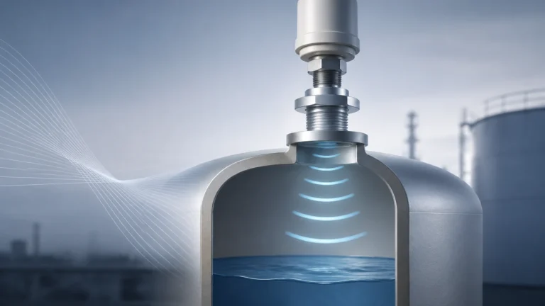
Radar sensors operate on the Time of Flight (ToF) principle. The sensor emits a high-frequency microwave signal (typically in the 6 GHz, 26 GHz, or 80 GHz range) toward the medium. The signal reflects off the surface of the product and returns to the antenna. The instrument calculates the level based on the time interval between emission and reception.
* 80 GHz Technology: The industry has shifted significantly toward 80 GHz radar. This high frequency allows for a much narrower beam angle (as small as 3°), which is crucial for avoiding internal tank obstructions like agitators, heating coils, or ladders. It also provides better reflection from media with low dielectric constants.
* 26 GHz Technology: Often used for larger antennas or applications where heavy foam or dust might attenuate higher-frequency signals.
Guided Wave Radar (GWR)
Guided Wave Radar also uses the ToF principle but directs the microwave pulse along a physical probe (cable or rod). This technology is particularly effective in applications with low dielectric constants, high turbulence, or where the vapor space above the liquid is inconsistent. GWR is a contact-based technology, meaning the probe must be compatible with the chemical properties of the medium.
Ultrasonic Level Sensors
Ultrasonic sensors emit acoustic pulses. The time it takes for the sound wave to bounce back determines the distance. While cost-effective, ultrasonic measurement is susceptible to environmental factors such as air temperature fluctuations, heavy foam, and vacuum conditions, as sound requires a medium (air) to travel.
Hydrostatic Pressure
Hydrostatic transmitters measure the pressure exerted by a liquid column. Since pressure is directly proportional to the height of the liquid and its density, the level can be calculated precisely. This method is highly reliable for vented or pressurized tanks but requires a constant or known density of the medium.
Technical Comparison of Technologies
Selecting the right instrument requires a comparison of how different technologies handle process variables. The following table outlines the general performance characteristics of the primary technologies utilized by major manufacturers like Vega America and Welk.
| Feature | 80 GHz Radar | Guided Wave Radar (GWR) | Ultrasonic | Hydrostatic |
| :— | :— | :— | :— | :— |
| Measurement Type | Non-contact | Contact | Non-contact | Contact |
| Accuracy | ±1 mm to ±2 mm | ±2 mm | ±0.2% of range | ±0.1% to ±0.2% |
| Max Range | Up to 120m | Up to 75m | Up to 15m | Varies by pressure |
| Pressure Range | Vacuum to 160 bar | Vacuum to 400 bar | Atmospheric | Up to 1000 bar |
| Temperature Range | -196°C to +450°C | -196°C to +450°C | -40°C to +80°C | -40°C to +400°C |
| Effect of Dust/Vapor | Minimal | None | High | None |
| Effect of Foam | Moderate (Frequency dep.) | Low | High | None |
| Media Density Change | No effect | No effect | No effect | Significant effect |
Application Engineering and Selection Criteria
When evaluating solutions from a provider like Vega America, engineers must confirm several process parameters to ensure the longevity and accuracy of the installation. The "one size fits all" approach rarely succeeds in complex industrial settings.
1. Dielectric Constant (εr)
For radar-based systems, the dielectric constant of the material is the most important factor. Materials with high εr (like water, εr ≈ 80) reflect signals strongly. Hydrocarbons and dry solids often have low εr (1.5 to 4.0), requiring more sensitive electronics and higher-frequency antennas to achieve a reliable signal-to-noise ratio.
2. Vessel Geometry and Internal Obstructions
In narrow silos or tanks with complex internal structures, the beam angle of the sensor is paramount. An 80 GHz radar sensor can often "see" past narrow gaps and avoid false reflections from walls or agitators that would confuse a lower-frequency sensor or an ultrasonic device.
3. Process Conditions (Temperature and Pressure)
Extreme temperatures require specialized seals (such as ceramic or PTFE) and cooling extensions. High-pressure applications necessitate robust housing and process connections (flanges or NPT threads) that meet ASME or DIN standards. Hydrostatic sensors used in corrosive environments often require exotic materials like Hastelloy or Tantalum for the diaphragm.
4. Media Characteristics
Is the material corrosive? Does it tend to build up on surfaces? For sticky liquids, non-contact radar is preferred to avoid maintenance issues associated with probe cleaning. For bulk solids, the angle of repose and dust generation must be considered; high-power radar pulses are typically required to penetrate heavy dust during filling cycles.
Installation Considerations for Optimal Performance
Even the most advanced sensor will fail if installed incorrectly. Based on engineering best practices for level measurement, the following guidelines should be followed:
* Nozzle Dimensions: The sensor antenna should ideally extend slightly beyond the bottom of the mounting nozzle to prevent "ringing" or internal reflections within the nozzle itself. If using a long nozzle, a radar with a narrower beam or a GWR is recommended.
* Positioning: Avoid mounting the sensor in the center of a tank with a domed top, as this can concentrate false reflections. Similarly, do not mount the sensor directly above the filling stream, as the turbulence and falling material will interfere with the signal.
* Obstruction Clearance: Maintain a clear "signal cone." For a sensor with a 10° beam angle, the diameter of the detection area increases by approximately 17 cm for every meter of distance. Ensure no pipes, ladders, or baffles enter this cone.
* Stilling Wells and Bypass Pipes: In applications with extreme turbulence or heavy foam, mounting the sensor inside a stilling well (a vertical pipe) can provide a calm surface for measurement. This is common in the oil and gas industry for storage tanks.

Limitations and Common Challenges
While technology has advanced, certain limitations remain that engineers should account for during the design phase:
1. Multiple Interfaces: Measuring the interface between two liquids (e.g., oil and water) requires Guided Wave Radar. Standard non-contact radar typically only sees the top surface unless the upper layer is non-conductive and thin.
2. Foam Attenuation: Very thick, dense foam can absorb radar signals entirely. In these cases, hydrostatic pressure or mechanical level switches may be more reliable.
3. Vacuum Conditions: Ultrasonic sensors cannot function in a vacuum because sound waves require a medium. Radar is unaffected by vacuum.
4. Condensation: Heavy condensation on a radar antenna can cause signal attenuation. Modern sensors often use convex lens antennas or PTFE coatings to encourage droplets to run off.
The Role of Specialized Manufacturers
While Vega America is a prominent name in the North American market, the global industrial sector relies on a variety of manufacturers to meet diverse needs. Companies like Welk provide a comprehensive range of level measurement instruments, including radar, ultrasonic, and hydrostatic transmitters, designed to offer high accuracy and cost-effectiveness. For many B2B applications, the choice comes down to a balance between technical specifications, local support, and total cost of ownership.
When sourcing instruments, it is beneficial to Review product options and application support to ensure the selected hardware aligns with the specific chemical and physical requirements of the process. Whether the application involves wastewater treatment, chemical processing, or food and beverage production, having access to a broad portfolio of sensing technologies allows for a more tailored engineering solution.
Frequently Asked Questions (FAQ)
Q: Can I use a radar sensor for solids and liquids interchangeably?
A: Generally, yes, but the configuration may differ. Solids measurement often requires a higher power output and a swiveling flange to aim the sensor at the material's angle of repose, whereas liquid measurement focuses on handling surface turbulence and foam.
Q: What is the benefit of a 4-20mA HART output versus Modbus or Profibus?
A: 4-20mA HART is the industry standard for simple integration into existing PLC/DCS systems, allowing for both an analog signal and digital diagnostics. Modbus and Profibus are preferred for digital networks where multiple sensors are daisy-chained over long distances.
Q: How often do radar level meters need calibration?
A: Radar sensors are solid-state and typically do not drift. Calibration is usually performed at commissioning to map out tank obstructions. Periodic verification is recommended depending on the facility's safety integrity level (SIL) requirements, but routine recalibration is rarely necessary.
Q: Is Guided Wave Radar better than Non-Contact Radar?
A: Neither is "better" overall; they are application-dependent. GWR is superior for interface measurement and low-dielectric liquids in small tanks. Non-contact radar is superior for corrosive media (as it doesn't touch the product) and very tall silos where a long cable probe would be impractical.
By adhering to these engineering principles and carefully evaluating the process environment, facilities can implement level measurement solutions that provide reliable data for years of operation. For further technical specifications and to explore a wide range of industrial level instruments, visit the Main Page of our product catalog.