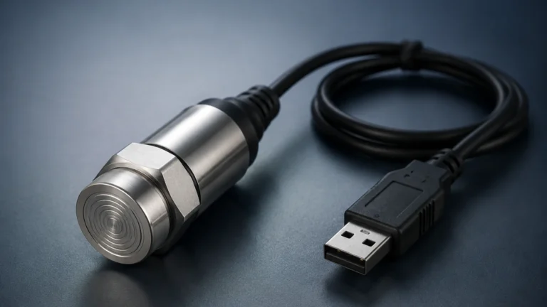
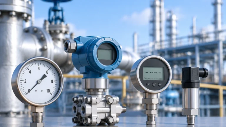
Vega Application
Vega Application
In the realm of industrial automation, the term "Vega application" frequently refers to the deployment of high-precision level measurement sensors in challenging process environments. Whether managing corrosive chemicals, volatile hydrocarbons, or bulk solids, selecting the right measurement technology is critical for operational safety and efficiency. This guide explores the engineering principles, selection criteria, and installation best practices for modern level measurement instruments, drawing on the technical standards established by industry leaders like Welk.
Core Principles of Level Measurement
Before selecting a device for a specific application, it is essential to understand the underlying physics of the most common measurement technologies. Each method has distinct advantages depending on the physical properties of the media and the vessel's environment.
Radar Level Measurement (Non-Contact)
Non-contact radar sensors, particularly those operating in the 80 GHz frequency range, are the cornerstone of modern level sensing. They function on the Time-of-Flight (ToF) principle. The sensor emits a high-frequency microwave signal toward the product surface. This signal is reflected back to the antenna. The instrument measures the time difference between emission and reception to calculate the distance.
Modern radar sensors often use Frequency Modulated Continuous Wave (FMCW) technology. Unlike simple pulse radar, FMCW transmits a continuous signal with a constantly changing frequency. This allows for much higher resolution and the ability to filter out "noise" from internal tank obstructions like agitators or ladders. This is a primary consideration in any complex vega application where precision is paramount.
Ultrasonic Level Sensors
Ultrasonic sensors also use the ToF principle but rely on sound waves rather than electromagnetic waves. A transducer emits an ultrasonic pulse that bounces off the liquid or solid surface. Because the speed of sound is affected by air temperature, these sensors typically include integrated temperature compensation. They are cost-effective solutions for water treatment and simple storage applications but are sensitive to vacuum, high pressure, and heavy foam.
Hydrostatic Level Transmitters
Hydrostatic measurement relies on the relationship between the height of a liquid column and the pressure it exerts at the base of the vessel. The formula used is $P = \rho \cdot g \cdot h$, where $P$ is pressure, $\rho$ (rho) is the density of the fluid, $g$ is gravity, and $h$ is the height. This method is highly reliable for vented tanks and deep wells where the density of the fluid remains constant.
Guided Wave Radar (GWR)
Guided Wave Radar uses a physical probe (cable or rod) to lead the microwave signal to the surface. This is particularly effective in applications with low dielectric constants or where the surface is turbulent. The signal remains concentrated along the probe, reducing energy loss and improving the signal-to-noise ratio in narrow nozzles.
Key Evaluation Criteria for Instrument Selection
When designing a system for a vega application, engineers must evaluate several variables to ensure the longevity and accuracy of the instrument. Failure to account for these can lead to signal loss or premature hardware failure.
1. Dielectric Constant ($ε_r$): For radar-based systems, the reflectivity of the material is determined by its dielectric constant. Water has a high $ε_r$ (~80), making it easy to detect. Hydrocarbons like oil have low $ε_r$ (~2), requiring high-sensitivity sensors or guided wave technology.
2. Process Temperature and Pressure: Standard sensors may operate up to 80°C, but specialized ceramic-PTFE seals are required for temperatures exceeding 200°C or pressures above 40 bar (4 MPa).
3. Vessel Geometry: Internal structures such as heating coils, baffles, and agitators can create false reflections. Narrow beam angles (e.g., 3° to 6°) provided by 80 GHz radar help avoid these obstacles.
4. Media Physical State: Is the material a liquid, a slurry, or a bulk solid? Bulk solids require sensors capable of handling uneven surfaces and dust, which can attenuate ultrasonic signals but are generally transparent to radar.
Practical Selection Table
The following table provides a quick reference for matching technology to common industrial scenarios.
| Application Type | Recommended Technology | Key Advantage | Limitation |
| :— | :— | :— | :— |
| Corrosive Chemical Tank | Non-contact Radar (PTFE) | No contact with media | High cost for exotic materials |
| Wastewater Sump | Ultrasonic | Cost-effective | Sensitive to steam/foam |
| Deep Well / Borehole | Hydrostatic | Simple installation | Requires constant density |
| High-Pressure Steam Boiler | Guided Wave Radar | Ignores steam/turbulence | Probe buildup can occur |
| Grain Silo | 80 GHz Radar | Penetrates dust | Requires aiming flange |
| Small Process Vessel | 80 GHz Radar | Small beam angle | Minimum blocking distance |
For more detailed technical specifications and to Review product options and application support, consulting a specialized manufacturer like Welk is recommended to ensure the hardware meets the specific demands of the process.
Installation Considerations and Best Practices
Correct installation is as important as selecting the right technology. Even the most advanced sensor will fail if it is poorly positioned.
Nozzle Dimensions
The mounting nozzle should be as short and wide as possible. For radar sensors, if the nozzle is too long, the signal may reflect off the internal walls of the pipe before reaching the tank, creating a "ringing" effect that masks the true level. Ideally, the antenna should extend slightly below the bottom of the nozzle.
Positioning and Clearance
* Avoid the Center: Never mount a sensor in the exact center of a circular tank, as this can cause multiple reflections to converge, leading to signal interference.
* Inflow Streams: Ensure the sensor is not located directly above the point where product enters the tank. Turbulence and air entrainment at the entry point will scatter the signal.
* Beam Path: Maintain a clear "corridor" for the signal. For a radar sensor with a 6° beam angle, the beam diameter expands as it travels. At a distance of 10 meters, the beam footprint is approximately 1.05 meters wide.
Dead Zones (Blocking Distance)
Every sensor has a "dead zone" or blocking distance near the antenna where measurement is not possible. For ultrasonic sensors, this might be 25 cm to 50 cm. For radar, it is often much smaller (under 10 cm). Ensure the maximum fill level of the tank does not enter this zone.

Limitations and Common Risks in Vega Applications
While modern instrumentation is highly robust, certain conditions present significant risks to measurement integrity.
* Heavy Foam: Foam can act as an absorber for both ultrasonic and radar signals. While low-frequency radar (6 GHz) can sometimes see through foam to the liquid below, high-frequency radar (80 GHz) might reflect off the top of the foam or lose the signal entirely if the foam is dense and conductive.
* Condensation and Buildup: In high-humidity environments, water droplets can form on the sensor face. While many modern antennas are designed with convex shapes to shed droplets, heavy buildup of viscous or crystallizing media will eventually attenuate the signal.
* Vacuum Conditions: Ultrasonic sensors cannot function in a vacuum because sound requires a medium (air or gas) to travel. Radar is unaffected by vacuum as electromagnetic waves travel freely in a vacuum.
* Gas Stratification: In tanks containing heavy gases or vapors (like CO2), the speed of sound can change, causing significant errors in ultrasonic measurements. Radar remains the preferred choice here as the speed of light is negligibly affected by gas composition.
Frequently Asked Questions (FAQ)
Q: Can I use a radar sensor for both liquids and solids?
A: Yes, but the configuration differs. For solids, the sensor often requires a higher power output and an aiming flange to account for the "angle of repose" (the slope of the material pile). Welk provides specialized versions of their radar meters for these distinct use cases.
Q: How often do these instruments need calibration?
A: Most digital radar and ultrasonic sensors do not "drift" in the traditional sense. However, a yearly verification is recommended to ensure that the internal electronics are functioning correctly and that no physical buildup has occurred on the antenna.
Q: What is the maximum range for these sensors?
A: High-end radar sensors can measure distances up to 120 meters (approx. 393 feet). Hydrostatic sensors are limited by the pressure rating of the diaphragm, often reaching depths of 200 meters in water applications.
Q: How do I handle measurement in a tank with a heavy agitator?
A: Use a sensor with a narrow beam angle and utilize "False Signal Suppression" (also known as echo mapping). This allows the software to record the reflections from the agitator blades and ignore them during the actual level calculation.
Conclusion for Engineering Teams
Successful implementation of a vega application requires a holistic view of the process. By understanding the physics of radar, ultrasonic, and hydrostatic measurement, engineers can select the most resilient tool for the job. It is vital to confirm the chemical compatibility of wetted parts (such as 316L stainless steel, Hastelloy, or PTFE) and the electrical classification of the area (ATEX/IECEx for hazardous zones) before procurement.
For professionals seeking reliable, accurate, and cost-effective level measurement solutions, the Main Page of Welk offers a comprehensive overview of industrial-grade instruments designed to meet these rigorous standards. Proper planning during the selection and installation phases ensures that the level measurement system provides years of maintenance-free service in even the most demanding industrial environments.