Vega Level Switch
Vega Level Switch
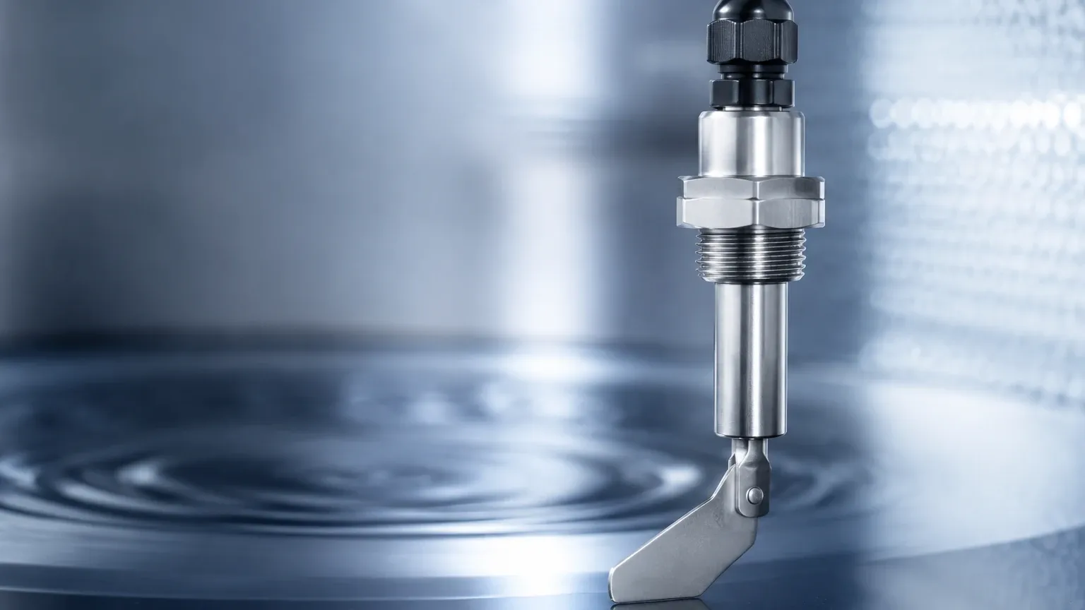
In industrial process automation, point level detection serves as a critical safeguard for preventing tank overfills, protecting pumps from dry running, and managing automated inventory thresholds. Among the various solutions available in the market, the vega level switch represents a diverse category of instruments designed to provide reliable switching signals across liquids, pastes, and bulk solids. Understanding the specific measurement principles, selection criteria, and installation requirements is essential for engineers tasked with maintaining process safety and efficiency.
Level switches are distinct from continuous level transmitters. While transmitters provide a constant 4-20mA or digital output representing the exact level, a switch provides a discrete binary output (on/off) when the medium reaches a specific point. This guide explores the technical landscape of these instruments and provides a framework for selecting the appropriate technology for demanding industrial environments.
Understanding the Measurement Principles of Vega Level Switches
To select the correct instrument, one must first understand the physical phenomena used to detect the presence of a medium. Different media properties—such as density, conductivity, and dielectric constant—dictate which sensing principle will be most effective.
Vibrating Fork (Tuning Fork) Principle
This is one of the most common technologies used in the vega level switch portfolio, often referred to as the vibrating level switch. The sensor consists of a tuning fork-shaped element that is piezoelectrically energized and vibrates at its mechanical resonance frequency in the air.
When the fork is submerged in a liquid or covered by solids, the frequency changes. For liquids, the frequency drops due to the increased density of the medium. For solids, the vibration is dampened or stopped entirely. An integrated electronic circuit detects this frequency shift and converts it into a switching command. This method is highly robust as it is largely independent of the chemical and physical properties of the liquid, such as pressure, temperature, or conductivity.
Capacitive Level Detection
Capacitive switches operate based on the electrical capacitance of a capacitor formed by the sensor electrode and the tank wall. As the medium fills the space between the electrode and the wall, the capacitance changes based on the dielectric constant (εr) of the material. This technology is particularly effective for detecting interfaces or for use in non-conductive liquids and bulk solids. Modern capacitive switches often include "active shield" technology to compensate for material buildup on the probe, which can otherwise cause false triggering.
Conductive Principle
Used primarily for conductive liquids (such as water or acids), conductive switches measure the electrical resistance between two electrodes. When the liquid touches both electrodes, a small current flows, triggering the switch. While simple and cost-effective, this method is limited to liquids with a minimum conductivity (typically >10 µS/cm) and is susceptible to errors if non-conductive coatings build up on the probes.
Microwave Barrier
For non-contact detection, microwave barriers are utilized. A transmitter sends a microwave beam to a receiver. If the beam is interrupted by a medium (such as a high level of bulk solids in a silo), the receiver detects the signal loss and switches. This is ideal for abrasive or extremely hot materials where physical contact with the sensor would lead to premature failure.
Key Selection Criteria for Industrial Applications
Choosing a vega level switch requires a detailed analysis of the process conditions. A mismatch between the sensor principle and the application can lead to frequent maintenance intervals or catastrophic process failures. Engineers should evaluate the following factors:
1. Media State and Density: Is the material a liquid, a light powder, or a heavy granulate? Vibrating forks for liquids require a minimum density (often around 0.5 g/cm³ or 31.2 lb/ft³), while versions for solids can handle much lower densities.
2. Process Temperature and Pressure: Standard switches may operate up to 150°C (302°F), but specialized high-temperature versions are required for steam applications or molten materials. Pressure ratings can range from vacuum to over 64 bar (928 psi).
3. Chemical Compatibility: The wetted parts (the parts of the sensor in contact with the medium) must be resistant to corrosion. Common materials include 316L stainless steel, Hastelloy, or plastic coatings like PFA or PP.
4. Hygienic Requirements: In food and pharmaceutical industries, sensors must feature hygienic connections (like Tri-Clamp) and surfaces polished to a specific roughness (Ra < 0.8 µm) to prevent bacterial growth.
Technical Comparison Table for Level Switch Technologies
| Technology | Suitable Media | Key Advantage | Limitation |
| :— | :— | :— | :— |
| Vibrating Fork | Liquids, Powders, Granulates | Independent of media properties; no calibration required. | Not suitable for very high viscosity or large solids that can wedge in the fork. |
| Capacitive | Liquids, Solids, Interfaces | Can detect through non-metallic tank walls; adjustable sensitivity. | Requires calibration; sensitive to changes in dielectric constant. |
| Conductive | Conductive Liquids | Low cost; simple installation. | Only for conductive media; prone to electrolytic corrosion in some fluids. |
| Microwave Barrier | Bulk Solids, Opaque Liquids | Non-contact; works through plastic or ceramic windows. | Requires clear line of sight between transmitter and receiver. |
| Hydrostatic | Liquids (as point level) | Reliable in deep tanks. | Primarily a continuous measurement technology; more complex for simple switching. |
Installation and Mounting Best Practices
Correct installation is as vital as sensor selection. Even the most advanced vega level switch will fail if mounted in a position that exposes it to mechanical damage or misleading process conditions.
Orientation and Positioning
* Lateral Mounting: When mounted on the side of a vessel, vibrating forks should be oriented so that the flat surfaces of the forks are parallel to the flow of the material. This prevents the medium from piling up on the forks, which could cause a delayed switch-off.
* Top Mounting: If mounted from the top, the length of the sensor probe must be accurately specified to reach the desired switching point. For solids, avoid mounting the sensor directly in the path of the filling stream, as the impact of falling material can damage the probe or cause false alarms.
Mechanical Considerations
* Nozzle Length: Ensure that the sensor extends far enough into the vessel. If the nozzle is too long, material can become trapped in the dead space, leading to "bridging" where the sensor remains covered even after the tank level has dropped.
* Cable Entry: Always point cable entries downward to prevent moisture from entering the housing via capillary action along the cable. Use a "drip loop" in the wiring to ensure water sheds away from the sensor head.
Managing Operational Challenges: Buildup, Foam, and Turbulence
Industrial processes are rarely "clean." Engineers must account for several common challenges that interfere with point level detection.
Material Buildup and Coating
In sticky or viscous applications, material can cling to the sensor. While vibrating forks have a degree of self-cleaning due to their high-frequency oscillation, heavy buildup can eventually dampen the vibration. In these cases, capacitive sensors with active shield technology or microwave barriers are often preferred. For a broader look at instruments designed to handle challenging coatings, including radar-based solutions, you may consult the Main Page for detailed technical comparisons.
Foam and Turbulence
Foam can be problematic for many technologies. A vibrating fork might detect dense foam as a liquid, while a capacitive sensor might ignore it depending on its dielectric properties. If the goal is to detect the liquid level *under* the foam, careful adjustment of the switching threshold is necessary. In turbulent tanks with agitators, the sensor should be installed behind a stilling well or a baffle to prevent mechanical stress and erratic switching.
Maintenance and Lifecycle Management
Modern level switches are largely maintenance-free, but periodic checks are recommended to ensure functional safety, especially in Overfill Protection (WHG) or Safety Instrumented Systems (SIS).
1. Visual Inspection: Check for corrosion on wetted parts and integrity of the housing seals.
2. Functional Test: Periodically raise the level or manually trigger the sensor to verify that the output relay or transistor correctly signals the control system.
3. Cleaning: If the application involves crystallizing or sticky media, scheduled cleaning of the sensing element may be required to prevent false triggers.
Frequently Asked Questions (FAQ)
Q: Can a vibrating level switch be used in highly aerated liquids?
A: Yes, but the density of the aerated liquid must remain above the sensor's minimum detection threshold (typically 0.5 g/cm³). If the aeration is so high that the density drops significantly, a capacitive or conductive switch may be more reliable.
Q: What is the difference between a PNP and an NPN output in a level switch?
A: These refer to the type of transistor output. PNP (Positive-Negative-Positive) switches connect the load to the positive supply, while NPN (Negative-Positive-Negative) switches connect the load to the negative (ground). PNP is more common in European and North American industrial PLC systems.
Q: How do I handle level switching in a plastic tank?
A: For plastic tanks, non-contact methods like microwave barriers or capacitive sensors that can "see" through the wall are ideal. Alternatively, standard switches can be used if they are mounted through a threaded or flanged nozzle.
Q: Is calibration required for a vega level switch?
A: Vibrating fork switches generally do not require calibration; they are "plug and play." Capacitive switches, however, usually require a simple adjustment to set the switching point based on the specific dielectric properties of the medium and the tank geometry.
By carefully matching the sensing principle to the physical properties of the medium and following rigorous installation standards, operators can ensure that their level switches provide the reliable, long-term performance required for modern industrial automation. For more information on selecting the right level measurement technology for your specific application, reviewing the technical specifications and application notes on the Welk Main Page is a recommended next step for process engineers.