Vega Machine
Vega Machine
In the landscape of industrial automation, the term "vega machine" often serves as a shorthand for high-precision level measurement instrumentation used to monitor liquids, solids, and gases within process vessels. These instruments are the backbone of inventory management, process safety, and efficiency in sectors ranging from water treatment to chemical processing. Selecting the correct level measurement technology requires a deep understanding of the physics behind the sensors, the environmental constraints of the application, and the long-term maintenance requirements of the hardware.
Welk, as a professional manufacturer of industrial level measurement instruments, provides a comprehensive suite of solutions including radar level meters, ultrasonic sensors, and magnetic level gauges designed to meet these rigorous industrial demands. This guide explores the principles, selection criteria, and installation nuances essential for engineers and procurement specialists evaluating level measurement machines.
Understanding Level Measurement Principles
Before selecting a specific vega machine or sensor type, it is critical to understand the operating principles that govern modern level detection. Most industrial level instruments fall into two categories: contact and non-contact measurement.
1. Time of Flight (ToF) – Radar and Ultrasonic
The most common principle used in high-end level measurement is Time of Flight. The instrument emits a signal (either an electromagnetic radar pulse or an ultrasonic sound wave) that travels to the surface of the medium, reflects, and returns to the sensor. The distance ($d$) is calculated using the formula:
$$d = \frac{v \times t}{2}$$
Where $v$ is the speed of the signal (speed of light for radar, speed of sound for ultrasonic) and $t$ is the measured time.
* Radar (FMCW/Pulse): Operates at high frequencies (typically 26GHz or 80GHz). Because radar uses electromagnetic waves, it is unaffected by vacuum, high pressure, or temperature fluctuations.
* Ultrasonic: Uses sound waves. It is cost-effective but sensitive to air temperature, heavy vapors, and vacuum conditions, as sound requires a medium to travel.
2. Hydrostatic Pressure
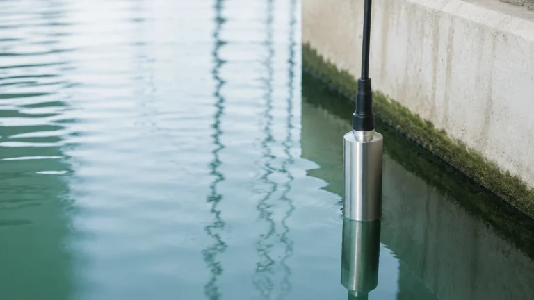
This principle relies on the relationship between the height of a liquid column and the pressure it exerts at the base. By measuring the pressure ($P$) and knowing the density ($\rho$) of the liquid, the level ($h$) can be determined:
$$h = \frac{P}{\rho \times g}$$
This is a reliable method for vented tanks where the density remains constant.
3. Magnetic Displacement
Magnetic level gauges utilize a float containing a permanent magnet. As the liquid level rises or falls, the float moves accordingly, actuating a series of magnetic flags or a transmitter outside the chamber. This provides a clear visual indication without requiring power, alongside electronic transmission for remote monitoring.
Key Technologies in Industrial Level Measurement
When evaluating a vega machine for a specific project, the choice usually narrows down to Radar or Ultrasonic technology due to their versatility and non-contact nature.
80GHz Radar Technology
The move toward 80GHz radar has revolutionized the industry. Compared to older 26GHz models, 80GHz instruments offer a much narrower beam angle (as small as 3°). This allows the signal to avoid internal tank obstructions like agitators, heating coils, or ladders, which previously caused false echoes. For complex vessel geometries, high-frequency radar is often the preferred choice.
Guided Wave Radar (GWR)
In applications where the dielectric constant of the medium is very low, or where there is heavy foam on the surface, Guided Wave Radar is used. A probe or cable guides the radar pulse directly to the surface. This ensures the signal strength is maintained, providing a reliable reading even in challenging conditions like boiling liquids or hydrocarbon storage.
Selection Criteria for Level Measurement Machines
Choosing the right instrument involves balancing technical requirements with budget constraints. The following table provides a comparison of common technologies based on typical industrial performance metrics.
| Technology | Typical Accuracy | Max Range | Max Temperature | Pressure Limit | Common Media |
| :— | :— | :— | :— | :— | :— |
| 80GHz Radar | ±2 mm | 120 m | +250°C | 4.0 MPa | Corrosive liquids, bulk solids, powders |
| 26GHz Radar | ±3-5 mm | 30 m | +150°C | 2.0 MPa | Water, wastewater, oils |
| Ultrasonic | ±0.25% FS | 15-30 m | +80°C | Atmospheric | Open channels, sumps, water tanks |
| Hydrostatic | ±0.5% FS | 200 m | +100°C | N/A | Deep wells, fuel tanks, reservoirs |
| Magnetic Gauge| ±5 mm | 6 m | +400°C | 16.0 MPa | Boilers, chemical reactors, oil/gas |
For a detailed technical review of specific sensor models and their application compatibility, professionals should consult the Main Page to review product options and application support.
Installation Best Practices
Even the most advanced vega machine will fail to perform if installed incorrectly. Proper physical placement is the single most important factor in ensuring long-term accuracy.
1. Nozzle Geometry
For radar and ultrasonic sensors, the nozzle should be as short and wide as possible. If the nozzle is too long, the signal may reflect off the internal walls of the pipe before reaching the tank, creating a "near-field" interference. The sensor face should ideally extend slightly below the nozzle bottom.
2. Beam Angle and Obstructions
Every non-contact sensor has a beam angle (e.g., 8°). The "footprint" of the signal expands as it travels deeper into the tank. Engineers must ensure that no internal structures (pipes, baffles, or agitator blades) enter this signal cone. If an obstruction is unavoidable, many modern instruments offer "false echo suppression" software to mask out these static reflections.
3. Blocking Distance (Dead Zone)
Every sensor has a minimum distance it cannot measure, known as the dead zone or blocking distance. For an ultrasonic sensor, this might be 0.25 meters to 0.5 meters. If the liquid level rises into this zone, the sensor will provide an error or an incorrect maximum reading. The instrument must be mounted high enough to account for the maximum expected fill level.
4. Orientation
Sensors should be mounted perpendicular to the liquid surface. In solids applications (like grain or cement silos), the surface is often angled (the angle of repose). In these cases, adjustable mounting flanges are used to aim the sensor at the most representative part of the material heap.

Limitations and Application Risks
While modern level measurement machines are highly robust, certain environmental factors can compromise their performance:
* Heavy Foam: Foam can absorb ultrasonic and radar signals, leading to signal loss. In these cases, Guided Wave Radar or Hydrostatic transmitters are superior alternatives.
* Dust and Steam: While radar can penetrate dust, heavy steam can occasionally attenuate the signal. High-frequency radar with a purging connection (to blow air across the lens) is often required in cement silos or hot chemical tanks.
* Vacuum Conditions: Ultrasonic sensors cannot function in a vacuum because sound waves require a medium (air/gas) to travel. Radar is the standard for vacuum distillation columns.
* Turbulence: Rapidly moving liquid surfaces can scatter the signal. Using a stilling well (a pipe that bypasses the turbulence) can provide a stable surface for the sensor to measure.
Maintenance and Calibration
Industrial level instruments are generally designed for low maintenance, but periodic checks are recommended. For radar and ultrasonic units, the sensor face should be inspected for buildup or condensation, particularly in sticky or crystallizing media.
Calibration should be verified annually. This is typically done by comparing the sensor's electronic output (4-20mA or digital HART signal) against a physical manual measurement (dip tape). If the instrument supports it, remote diagnostics can be used to monitor signal strength (amplitude), which serves as an early warning for potential sensor fouling.
Frequently Asked Questions (FAQ)
Q: Can a radar vega machine measure the interface between oil and water?
A: Yes, Guided Wave Radar (GWR) is specifically designed for this. It can detect the top of the oil layer and the interface where the water begins, provided the upper liquid has a lower dielectric constant than the lower liquid.
Q: What is the benefit of a 4-20mA HART output?
A: The 4-20mA signal provides the level reading, while the HART (Highway Addressable Remote Transducer) protocol allows for digital communication over the same wires. This enables remote configuration, diagnostics, and multi-variable reporting without additional wiring.
Q: How does temperature affect ultrasonic level sensors?
A: The speed of sound changes with air temperature. Most professional ultrasonic sensors include an integrated temperature probe to automatically compensate for these changes, but they may struggle if there are significant temperature gradients within the tank.
Q: Is it possible to measure level in a pressurized tank?
A: Yes. Radar and Magnetic Level Gauges are ideal for pressurized environments. Hydrostatic sensors can also be used if they are configured as differential pressure (DP) systems to account for the headspace pressure.
Conclusion
Selecting a vega machine for industrial level measurement is a process of matching the physics of the sensor to the realities of the plant environment. Whether utilizing the precision of 80GHz radar or the rugged simplicity of a magnetic level gauge, understanding the limitations and installation requirements is key to process safety. Welk continues to provide advanced, cost-effective measurement solutions tailored to these diverse industrial needs. For further technical specifications and to explore the full range of available instrumentation, please visit the Main Page.