Water Level Radar Sensor
Water Level Radar Sensor
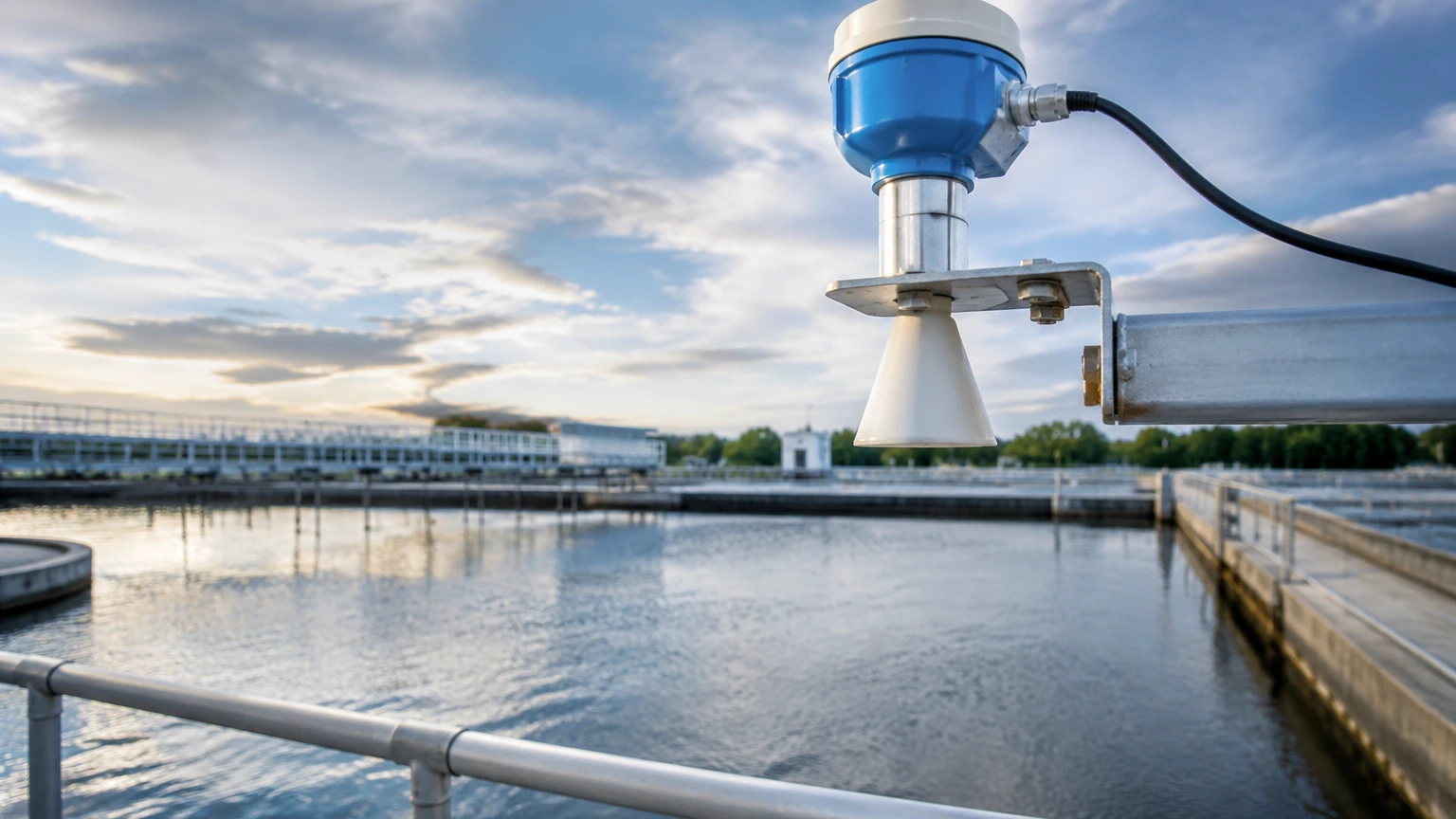
In modern industrial automation and environmental monitoring, the water level radar sensor has emerged as a primary instrument for non-contact level measurement. Unlike traditional contact-based methods, radar technology utilizes electromagnetic waves to determine the distance to a liquid surface, offering high precision and reliability in challenging environments. This guide examines the technical principles, selection criteria, and practical installation requirements for radar-based water level measurement in B2B applications such as water treatment, chemical processing, and hydrological monitoring.
Measurement Principles: How Radar Sensors Function
To select the appropriate water level radar sensor, engineers must first understand the two primary technologies used in radar level measurement: Pulse Radar and Frequency Modulated Continuous Wave (FMCW).
Pulse Radar (Time of Flight)
Pulse radar sensors emit short microwave pulses toward the water surface. These pulses travel at the speed of light, reflect off the surface, and return to the sensor's antenna. The instrument measures the "Time of Flight" (ToF)—the time elapsed between emission and reception. Since the speed of light is constant, the distance is calculated using the formula:
*Distance = (Speed of Light × Time of Flight) / 2*
Pulse radar is often favored for its lower power consumption, making it suitable for battery-powered or solar-powered remote hydrological stations.
FMCW Radar (Frequency Modulated Continuous Wave)
FMCW radar sensors emit a continuous signal with a constantly changing frequency (a frequency sweep). When the reflected signal is received, it is compared with the signal currently being emitted. The frequency difference between the transmitted and received signals is directly proportional to the distance.
FMCW technology, particularly at higher frequencies like 80GHz, provides significantly higher resolution and accuracy compared to pulse radar. This makes it the preferred choice for industrial tanks where precision within ±2mm is required. For more information on various radar configurations, engineers can visit the Main Page of specialized manufacturers.
Comparison: Radar vs. Other Level Technologies
Understanding why a water level radar sensor is chosen over ultrasonic or hydrostatic sensors is critical for project specification.
| Feature | Radar Sensor | Ultrasonic Sensor | Hydrostatic Transmitter |
| :— | :— | :— | :— |
| Measurement Type | Non-contact (EM Waves) | Non-contact (Sound Waves) | Contact (Pressure) |
| Atmospheric Impact | None (Vacuum/Pressure) | High (Temp/Vapor/Wind) | None |
| Accuracy | High (up to ±1mm) | Moderate (±0.25% FS) | Moderate (±0.1% to 0.5%) |
| Maintenance | Very Low | Low | Moderate (Silt/Corrosion) |
| Media Density | Irrelevant | Irrelevant | Critical for Calibration |
| Cost | Higher Initial | Moderate | Lower Initial |
Radar sensors excel because electromagnetic waves do not require a medium for propagation. Unlike ultrasonic sensors, which are affected by air temperature fluctuations, heavy wind, or steam, radar signals remain stable regardless of the gas phase composition above the water.
Key Evaluation Criteria for Selection
When specifying a water level radar sensor for an industrial project, the following technical parameters must be evaluated:
1. Frequency (6GHz, 26GHz, and 80GHz)
* 6GHz (C-Band): Best for applications with heavy foam or turbulence, as the longer wavelength can penetrate surface agitation more effectively.
* 26GHz (K-Band): The traditional industrial standard, offering a balance between beam focus and signal strength. Suitable for most storage tanks and open channels.
* 80GHz (W-Band): The modern standard for high precision. It features a very narrow beam angle (often as small as 3°), allowing it to avoid internal obstructions like ladders, pipes, or agitators.
2. Beam Angle and Antenna Design
The beam angle determines the "footprint" of the radar signal. A narrow beam is essential for narrow tanks or deep wells to prevent false echoes from the walls. Antenna types include:
* Horn Antennas: Ideal for high-temperature or high-pressure industrial tanks.
* Lens Antennas: Often used in 80GHz sensors; they are flat and easy to clean, making them suitable for wastewater or corrosive liquids.
* Parabolic Antennas: Used for extremely long-range measurements (up to 70 meters or 230 feet) in large reservoirs or dam monitoring.
3. Dielectric Constant (εr)
Radar relies on the reflection of waves. Water has a high dielectric constant (approximately 80 at 20°C), which provides an excellent reflective surface for radar waves. However, if the water contains high concentrations of oil or foam, the reflection may be weakened, necessitating a sensor with higher sensitivity or a lower frequency.
Installation Considerations and Best Practices
Proper installation is the most significant factor in ensuring the long-term accuracy of a water level radar sensor. Engineers should adhere to the following guidelines:
Mounting Position
* Avoid the Center: In cylindrical tanks, do not mount the sensor in the exact center, as multiple reflections from the tank walls can converge and interfere with the signal.
* Distance from Wall: Maintain a minimum distance from the tank wall (typically 200mm to 500mm depending on the beam angle) to prevent side-lobe interference.
* Inlet Interference: Ensure the sensor is not mounted directly above the water inlet, as the turbulence and air entrainment from the inflowing water will cause signal instability.
Beam Clearance
The "signal cone" must be clear of obstructions. If a ladder, pipe, or heating coil is located within the beam path, the sensor will detect it as the water level. While many modern sensors from manufacturers like Welk include "False Echo Suppression" software to ignore these fixed objects, it is best practice to provide a clear line of sight to the water surface.
Dead Zones (Blocking Distance)
Every radar sensor has a minimum measurement distance, often called the "dead zone" or "blocking distance." This is typically between 50mm and 300mm from the antenna face. The sensor cannot accurately measure water that rises into this zone. Ensure the mounting nozzle or bracket is high enough to accommodate the maximum expected water level.
Common Risks and Limitations
While highly versatile, radar technology is not without limitations. Project managers should account for the following risks:
1. Heavy Foam: While radar can penetrate some foam, extremely thick, dense foam (like that found in some wastewater aeration tanks) can absorb the radar signal entirely, leading to a "loss of echo." In these specific cases, a 6GHz radar or a guided wave radar (GWR) might be more appropriate.
2. Condensation and Buildup: In high-humidity environments, water droplets can form on the antenna. While many lens-style antennas are designed to shed droplets, heavy buildup of minerals or biological growth can attenuate the signal. Regular inspection is recommended in wastewater applications.
3. Signal Bypassing: In very small diameter pipes or bypass chambers, the radar signal can interact with the pipe walls, requiring the use of a specialized "stillpipe" or guided wave radar.
Information to Confirm Before Procurement
Before finalizing a purchase or project specification, the following data points should be confirmed with the equipment manufacturer:
* Measurement Range: What is the maximum distance from the sensor to the lowest possible water level? (Standard ranges are 10m, 30m, or 70m).
* Process Connection: Is a flange, thread (NPT/G), or bracket required?
* Output Signal: Does the system require 4-20mA (HART), Modbus RS485, or wireless transmission (LoRaWAN/NB-IoT) for remote monitoring?
* Environmental Rating: Does the housing need to be IP68 for submersion or explosion-proof (Ex d / Ex ia) for hazardous chemical zones?
* Power Supply: Is 24V DC available, or must the sensor operate on a 3.6V battery or solar power?
Frequently Asked Questions (FAQs)
Q: Can a water level radar sensor measure through a plastic tank lid?
A: Yes. Since plastic (like PE or PP) has a low dielectric constant, radar waves can pass through the lid. This allows for measurement without cutting a hole in the tank, provided the lid is not metallic and the material is not too thick.
Q: How does wind affect the measurement in open river applications?
A: Unlike ultrasonic sensors, radar is unaffected by wind. The electromagnetic waves travel at the speed of light and are not displaced by air movement. However, extreme wind causing high waves on the water surface may require the sensor's damping software to be adjusted to provide a stable average reading.
Q: Is calibration required frequently?
A: No. Radar sensors are generally considered "maintenance-free" regarding calibration. Once the zero and span points are set during commissioning, the sensor will remain accurate because the speed of electromagnetic waves is a physical constant.
Q: What is the difference between 2-wire and 4-wire radar sensors?
A: A 2-wire sensor uses the same two wires for both power supply and the 4-20mA output signal, which simplifies wiring. A 4-wire sensor uses separate pairs for power and signal, which is often necessary for sensors with high power requirements, such as those with integrated displays or heating elements.
For engineers seeking specific technical data sheets or customized OEM solutions, reviewing the Main Page of a dedicated manufacturer like Welk provides access to detailed performance curves and housing options suited for diverse industrial landscapes.