Liquid Level Control System
Liquid Level Control System
In industrial process automation, a liquid level control system is a fundamental architecture used to monitor and regulate the height of liquids within tanks, silos, or open channels. These systems are critical for ensuring operational safety, optimizing production efficiency, and preventing environmental hazards such as overflows or dry-running pumps. A robust control system integrates primary sensing elements, controllers (such as PLCs or PID controllers), and final control elements like valves or variable frequency drives (VFDs).
Choosing the correct instrumentation requires a deep understanding of measurement principles, fluid dynamics, and the specific environmental constraints of the application. This guide examines the technical foundations of level measurement and the criteria for designing an effective control loop.
Measurement Principles and Technologies
Before selecting components for a liquid level control system, it is essential to understand how different sensors interact with the process media. Level measurement is generally categorized into point level detection and continuous level measurement.
Radar Level Measurement (FMCW and Pulse)
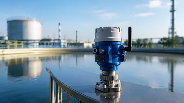
Radar level meters represent the high-end spectrum of non-contact measurement. They operate by emitting electromagnetic waves (microwaves) toward the liquid surface. The time it takes for the signal to reflect back to the sensor is used to calculate the distance.
Modern systems often utilize Frequency Modulated Continuous Wave (FMCW) technology. In FMCW, the transmitter emits a continuous signal with a constantly changing frequency. The difference in frequency between the emitted and received signal is proportional to the distance. Radar is highly effective in high-pressure and high-temperature environments because electromagnetic waves do not require a medium for propagation and are largely unaffected by air temperature or vapor layers.
Ultrasonic Level Measurement
Ultrasonic sensors function by emitting high-frequency sound pulses. These pulses reflect off the liquid surface and return to the transducer. The sensor calculates the distance based on the speed of sound. While cost-effective and reliable for water treatment and simple chemical storage, ultrasonic measurement is sensitive to the medium's atmosphere. Since sound speed varies with air temperature and density, integrated temperature compensation is required. Furthermore, heavy foam or significant dust can absorb the acoustic signal, leading to measurement errors.
Hydrostatic Pressure Measurement
Hydrostatic level transmitters measure the pressure exerted by a liquid column at a specific depth. According to the hydrostatic law, pressure ($P$) is equal to the product of liquid density ($
ho$), gravity ($g$), and the height of the liquid ($h$): $P = \rho gh$.
This method is widely used in deep wells and large storage tanks. It can be implemented using submersible probes or flange-mounted pressure transmitters at the bottom of the vessel. One critical limitation is that any change in the liquid's specific gravity (density) will directly impact the accuracy of the level reading unless the controller is programmed to compensate for these fluctuations.
Magnetic Level Gauges
Magnetic level gauges are based on the principle of buoyancy and magnetic coupling. A float containing a permanent magnet moves up and down a bypass chamber connected to the process vessel. Outside the chamber, a magnetic indicator or a series of reed switches tracks the float's position. This provides a clear visual indication and can be equipped with transmitters for remote monitoring. They are preferred in high-risk applications where power failure must not result in a total loss of level visibility.
Designing the Control Loop
A liquid level control system typically operates as a closed-loop feedback system. The process begins with the level sensor providing a real-time signal (usually 4-20mA, HART, or Modbus) to the controller.
1. Sensing: The transmitter (Radar, Ultrasonic, or Hydrostatic) measures the current level.
2. Comparison: The controller compares the measured value (Process Variable) against the desired Setpoint.
3. Calculation: A PID (Proportional-Integral-Derivative) algorithm calculates the necessary correction to minimize the error.
4. Action: The controller sends a signal to the final control element—such as opening a feed valve or increasing the speed of a discharge pump.
For basic safety, point level switches are often integrated as redundant interlocks to trigger emergency shutdowns if the continuous control loop fails.
Practical Selection Table
The following table provides a comparison of common technologies used in a liquid level control system to assist in the initial engineering phase.
| Technology | Measurement Type | Accuracy | Best For | Main Limitation |
| :— | :— | :— | :— | :— |
| Radar (80GHz) | Continuous | ±1 mm | Corrosive chemicals, high temp | High initial cost |
| Ultrasonic | Continuous | ±0.25% of range | Water, wastewater, acids | Affected by foam and vapor |
| Hydrostatic | Continuous | ±0.1% to 0.5% | Deep wells, vented tanks | Dependent on fluid density |
| Magnetic Gauge | Visual/Continuous | ±5 mm to 10 mm | Boilers, oil/gas tanks | Mechanical wear over time |
| Float Switch | Point Level | N/A | Pump start/stop, alarms | Moving parts can clog |
Installation Considerations
Correct installation is as vital as selecting the right technology. Even the most advanced radar meter will fail if mounted incorrectly. Engineers should review the Main Page of the equipment manufacturer for specific mounting drawings and clearance requirements.
Dead Zones (Blocking Distance)
Every non-contact sensor (Radar and Ultrasonic) has a "dead zone" or "blocking distance" directly beneath the sensor where it cannot measure. If the liquid level enters this zone, the sensor may report an error or a fixed maximum value. Ensure the sensor is mounted high enough so the maximum expected liquid level never enters the dead zone.
Obstructions and False Reflections
In tanks with internal structures like agitators, ladders, or heating coils, sensors must be positioned to avoid these obstructions. For radar and ultrasonic units, many modern transmitters include "false echo suppression" software, allowing the user to map out static reflections so the sensor ignores them.
Turbulence and Foam
If the liquid surface is turbulent due to high-speed filling or agitation, a stilling well or bypass pipe may be required. This creates a calm surface for the sensor to measure. Foam poses a particular challenge; while high-frequency radar can often penetrate light foam, ultrasonic signals are usually reflected or absorbed by it.

Limitations and Common Risks
While modern liquid level control systems are highly sophisticated, they are not infallible. Understanding the boundaries of the technology prevents system failure.
* Dielectric Constant ($D_k$): For radar measurement, the liquid must have a high enough dielectric constant to reflect the microwave signal. Non-conductive liquids like certain oils have low $D_k$ values, which may require specialized guided wave radar or larger antenna sizes.
* Vapor and Condensation: In closed tanks, condensation can form on the sensor face. While many radar sensors use PTFE lenses to shed droplets, heavy condensation can still attenuate the signal. Ultrasonic sensors are particularly prone to failure in high-steam environments.
1. Pressure Variations: Hydrostatic sensors in sealed tanks require a differential pressure setup to account for the gas pressure above the liquid. Failure to compensate for tank pressure will result in a completely incorrect level reading.
Frequently Asked Questions (FAQ)
Q: How often should a level transmitter be calibrated?
A: Calibration frequency depends on the criticality of the process and the technology used. Hydrostatic and mechanical systems generally require annual calibration. Radar and ultrasonic systems are more stable but should be verified every 12 to 24 months.
Q: Can one sensor handle both liquid and solid measurement?
A: Some radar and ultrasonic units are designed for both, but the configuration is different. Solids typically have an angle of repose that requires different beam angles and signal processing compared to the flat surface of a liquid.
Q: What is the benefit of using 80GHz radar over 26GHz?
A: 80GHz radar has a much narrower beam angle. This makes it easier to install in small nozzles and allows it to avoid internal tank obstructions more effectively than lower-frequency models.
Q: Is a liquid level control system compatible with Industry 4.0?
A: Yes. Most modern transmitters support digital protocols like HART, Profibus, or Foundation Fieldbus, allowing for remote diagnostics, predictive maintenance, and integration into cloud-based monitoring platforms.
Final Engineering Check
Before finalizing the design of a liquid level control system, project managers and engineers should confirm the following data points:
* Media Compatibility: Is the sensor material (316L, PTFE, PP) resistant to the process fluid?
* Process Conditions: What are the maximum and minimum operating pressures and temperatures?
* Vessel Geometry: Are there drawings showing the location of inlets, outlets, and internal baffles?
* Output Requirements: Does the control system require a simple 4-20mA loop, or is digital communication necessary for diagnostic data?
By systematically evaluating these factors and adhering to the physical principles of measurement, facilities can implement a liquid level control system that provides long-term reliability and precise process control.