Water Level Transducer
Water Level Transducer
In industrial automation and fluid management, the water level transducer serves as a critical bridge between physical liquid states and digital control systems. These instruments are engineered to convert the height or volume of water into a standardized electrical signal, such as 4-20mA, 0-10V, or digital protocols like RS485 Modbus. For engineers and facility managers, selecting the correct transducer is not merely a matter of measuring depth; it is about ensuring long-term system reliability, process safety, and data accuracy across diverse environments ranging from municipal wastewater plants to high-pressure chemical reactors.
As a professional manufacturer, Welk provides a broad spectrum of measurement technologies designed to meet these industrial demands. Understanding the underlying physics of each sensing method is the first step in optimizing a level control loop. For detailed technical specifications and a full range of instrument options, professionals can visit the Main Page of our product catalog.
Measurement Principles of Water Level Transducers
Before selecting a device, it is essential to understand how different transducers interpret "level." The most common industrial methods include hydrostatic pressure, ultrasonic time-of-flight, and radar wave reflection.
Hydrostatic Pressure (Submersible)
Hydrostatic water level transducers operate on the principle that the pressure at a specific depth is directly proportional to the weight of the liquid column above it. The relationship is defined by the formula:
P = ρ · g · h
Where *P* is pressure, *ρ* is the liquid density, *g* is gravity, and *h* is the height of the liquid.
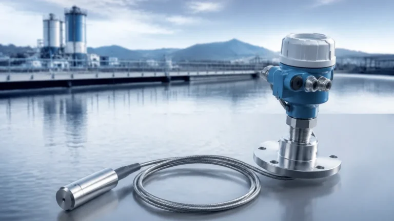
These sensors typically feature a stainless steel or ceramic diaphragm. As the water level rises, the pressure increases, deforming the diaphragm and changing the electrical resistance of an internal bridge circuit. A critical component of a hydrostatic water level transducer is the atmospheric compensation tube—a small vent line inside the signal cable that allows the sensor to subtract local barometric pressure from the total pressure, ensuring only the water column's weight is measured.
Ultrasonic (Non-Contact)
Ultrasonic transducers use high-frequency sound waves (typically 20 kHz to 200 kHz). The sensor emits a pulse that travels through the air, hits the water surface, and reflects back to the receiver. By measuring the time-of-flight (ToF) and knowing the speed of sound, the device calculates the distance to the water surface. Because they do not touch the liquid, ultrasonic sensors are ideal for corrosive or dirty water applications where contact-based sensors might fail due to buildup.
Radar (Microwave)
Similar to ultrasonic sensors, radar transducers use time-of-flight, but they employ electromagnetic waves (microwaves) instead of sound. Radar is particularly effective in environments where air temperature, pressure, or steam would interfere with sound waves. High-frequency radar (e.g., 80 GHz) offers extremely narrow beam angles, allowing for precise measurement even in narrow tanks with internal obstructions like ladders or agitators.
Practical Selection Criteria
Choosing the right water level transducer requires a thorough evaluation of the application's physical and chemical environment. Engineers should prioritize the following criteria:
1. Measurement Range: Determine the maximum depth (e.g., 5 meters, 50 meters, or 200 meters). Hydrostatic sensors are often preferred for very deep wells, while radar is excellent for tall, narrow silos.
2. Media Compatibility: While "water" sounds simple, industrial water can be deionized, brackish, or laden with sulfuric acid. Ensure the housing material (304SS, 316L, or PTFE) and cable jacket (PUR, PE, or FEP) are compatible with any chemical additives.
3. Accuracy Requirements: Standard industrial applications often require 0.5% Full Scale (FS) accuracy, but custody transfer or high-precision laboratory tests may require 0.1% FS or better.
4. Output Signal: Most legacy systems use 4-20mA analog loops, but modern IoT-integrated facilities may require RS485 (Modbus) or wireless protocols like LoRaWAN for remote monitoring.
5. Environmental Conditions: Consider the presence of foam, steam, or turbulence. Foam can absorb ultrasonic signals, whereas radar or hydrostatic sensors remain largely unaffected.
Technology Comparison Table
| Feature | Hydrostatic Transducer | Ultrasonic Transducer | Radar Transducer |
| :— | :— | :— | :— |
| Measurement Type | Contact (Submerged) | Non-Contact | Non-Contact |
| Standard Accuracy | ±0.25% to ±0.5% FS | ±0.25% FS | ±0.1% FS |
| Installation | Dropped into liquid | Top-mounted | Top-mounted |
| Max Range | Up to 500m H2O | Typically up to 20m | Up to 120m |
| Best For | Deep wells, boreholes | Open channels, sumps | Chemical tanks, steam |
| Limitations | Affected by density | Affected by foam/wind | Higher initial cost |
Installation Considerations and Best Practices
Proper installation is as vital as the sensor technology itself. Even the most accurate water level transducer will provide erratic data if installed incorrectly.
For Hydrostatic Submersible Sensors
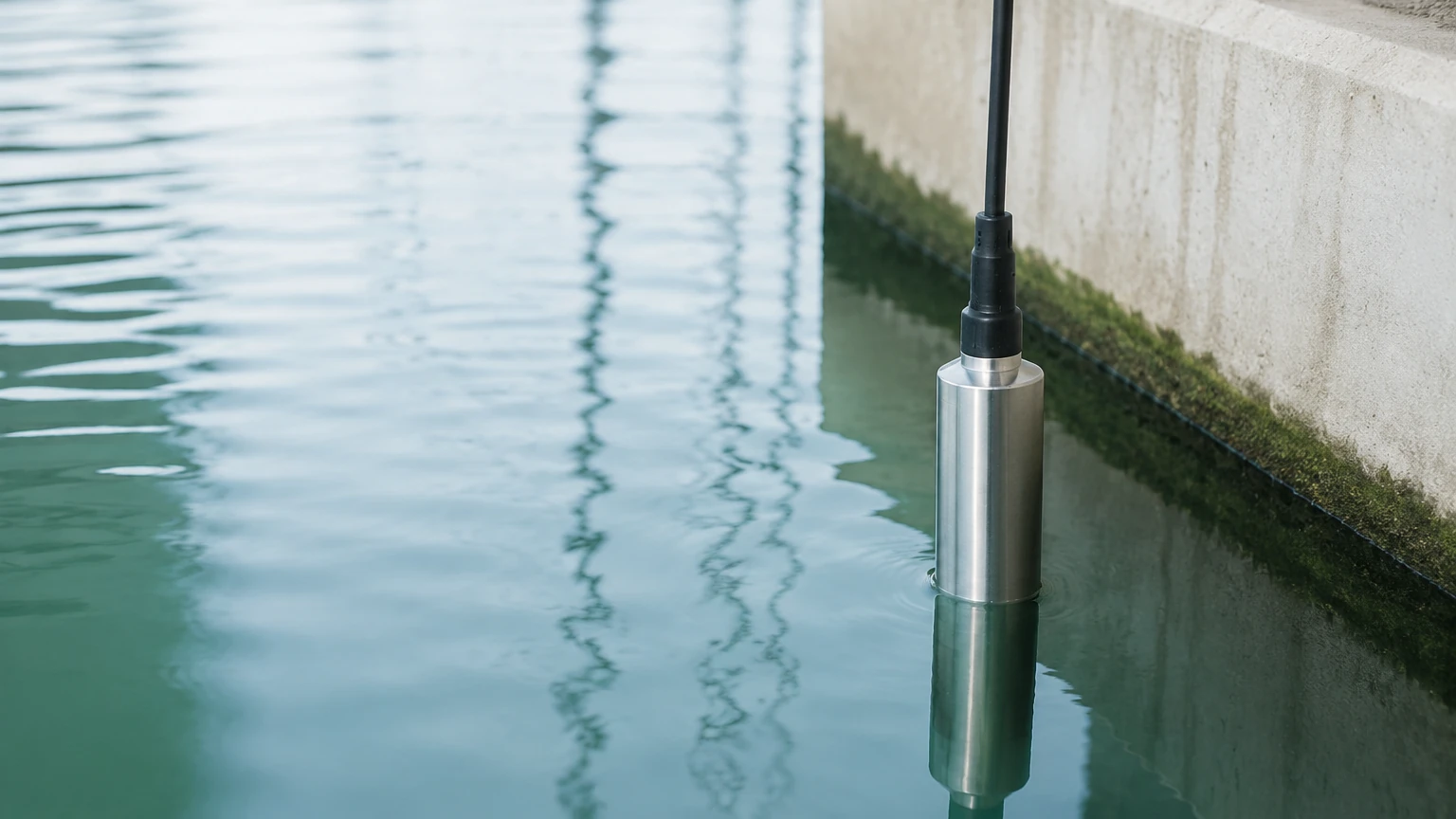
* Avoid Turbulence: Do not install the sensor near an inlet pipe or pump intake. The kinetic energy of moving water can create localized pressure fluctuations. If turbulence is unavoidable, use a stilling well (a perforated pipe) to protect the sensor.
* Cable Management: Ensure the cable is supported by a strain-relief clamp. Never allow the weight of the sensor to be supported solely by the electrical connections.
* Venting: The atmospheric vent tube must remain clear. Use a desiccant cartridge or a specialized vent filter to prevent moisture from entering the tube, which can lead to internal corrosion and signal drift.
For Non-Contact (Ultrasonic/Radar) Sensors
* Dead Zone: Every non-contact sensor has a "dead zone" (blocking distance) directly below the transducer face where it cannot measure. Ensure the sensor is mounted high enough that the water level never enters this zone.
* Beam Path: Ensure there are no obstructions (pipes, brackets, or wall ridges) within the signal's beam angle. For ultrasonic sensors, the beam is typically wider (10°-12°), while modern radar can be as narrow as 3°.
* Perpendicular Alignment: The sensor face must be perfectly parallel to the water surface to ensure the reflected signal returns directly to the receiver.
Limitations and Common Risks
While water level transducers are robust, they are not immune to environmental challenges. Awareness of these risks allows for better system design.
* Density Fluctuations: Hydrostatic sensors assume a constant liquid density. If the water temperature changes significantly or if the salinity increases, the density (ρ) changes, leading to a linear error in level calculation. In these cases, temperature-compensated sensors or non-contact methods are preferred.
* Signal Noise: In industrial settings, VFDs (Variable Frequency Drives) and heavy machinery can introduce electrical noise into 4-20mA loops. Using shielded twisted-pair cabling and ensuring proper grounding is essential to maintain signal integrity.
* Build-up and Fouling: In wastewater applications, fats, oils, and grease (FOG) can coat the diaphragm of a hydrostatic sensor or the face of an ultrasonic transducer. Regular maintenance schedules or the use of flush-diaphragm designs can mitigate this risk.
* Lightning and Surges: Since many water level transducers are installed in outdoor tanks or deep wells, they are susceptible to lightning strikes. Welk recommends using surge protection modules at both the sensor head and the control panel.
Frequently Asked Questions (FAQ)
Q: Can a water level transducer measure other liquids?
A: Yes, provided the materials of construction are compatible. However, for hydrostatic sensors, the device must be recalibrated for the specific gravity of the new liquid.
Q: How often should a transducer be calibrated?
A: For most industrial applications, an annual calibration check is sufficient. In critical safety or high-accuracy billing applications, semi-annual calibration is recommended.
Q: What is the difference between a level transmitter and a level transducer?
A: In common industry usage, the terms are often used interchangeably. Technically, a transducer converts one form of energy to another (e.g., pressure to voltage), while a transmitter conditions that signal for long-distance transmission (e.g., 4-20mA).
Q: How do I protect the sensor from freezing?
A: Submersible sensors should be installed below the frost line. For non-contact sensors in outdoor tanks, internal heating elements or insulated enclosures may be required to prevent ice formation on the sensor face.
Final Confirmation Before Implementation
Before finalizing a purchase or project specification, technical teams should confirm the following data points to ensure the chosen water level transducer is fit for purpose:
1. Tank/Well Geometry: Is there enough clearance for the beam angle, or is a submersible sensor the only viable option due to space constraints?
2. Power Supply Availability: Most transducers require 12-36V DC. Ensure the control system can provide stable power, especially for long cable runs where voltage drop may occur.
3. Process Temperature and Pressure: Confirm that the maximum possible process temperature does not exceed the sensor's operating limit (typically 80°C for standard models, higher for specialized versions).
4. Local Display Needs: Does the operator need to see the level at the tank site, or is the signal only sent to a central PLC/SCADA system?
By carefully matching the measurement principle to the environmental realities of the site, engineers can ensure that their water level transducer provides accurate, maintenance-free service for years. For further assistance in selecting the specific model for your application, please refer to the Main Page for comprehensive technical documentation and support.