Water Turbidity Sensor
Water Turbidity Sensor
In industrial process control and environmental monitoring, the measurement of suspended solids is a critical parameter for ensuring water quality and process efficiency. A water turbidity sensor is an optoelectronic device designed to quantify the cloudiness or haziness of a liquid caused by individual particles (suspended solids) that are generally invisible to the naked eye. This measurement is vital in applications ranging from municipal drinking water treatment to complex chemical processing and wastewater management.
Understanding the technical nuances of turbidity measurement allows engineers to select the appropriate instrumentation for their specific environmental conditions. As a professional manufacturer of industrial measurement solutions, Welk provides high-precision instruments that integrate seamlessly into automated systems, ensuring that data remains accurate even in challenging industrial environments.
Measurement Principles of Turbidity Sensors
Turbidity is not a direct measurement of the weight or concentration of suspended particles; rather, it is an optical property that describes how light interacts with those particles. When a light beam passes through a fluid sample, suspended solids scatter and absorb the light. The intensity of the scattered light is proportional to the amount of suspended matter present.
Nephelometry (90-Degree Scattering)
The most common method for measuring low to medium turbidity levels is nephelometry. In this design, a light source (typically an infrared LED or a tungsten lamp) sends a beam into the water. A detector is positioned at a 90-degree angle relative to the light path. This configuration is highly sensitive to the light scattered by small particles and is the standard for drinking water applications. The results are typically expressed in Nephelometric Turbidity Units (NTU) or Formazin Nephelometric Units (FNU).
Light Attenuation (Transmission)
For high-turbidity applications, such as sludge monitoring or industrial wastewater, the 90-degree scattering method may become saturated because the light cannot penetrate deep enough into the sample. In these cases, sensors use the transmission or attenuation principle. The detector is placed directly opposite the light source (at 180 degrees). The sensor measures the decrease in light intensity as it travels through the medium. This method is more effective for measuring high concentrations of solids where light scattering is too intense for nephelometric sensors.
Backscattering
In extremely dense media, some sensors utilize backscattering, where the detector is placed at an obtuse angle (e.g., 135 degrees) or even near the light source. This captures light reflected back from the surface layer of the particles, allowing for the measurement of very high suspended solids concentrations that would otherwise block a transmitted beam entirely.
Key Components and Design Considerations
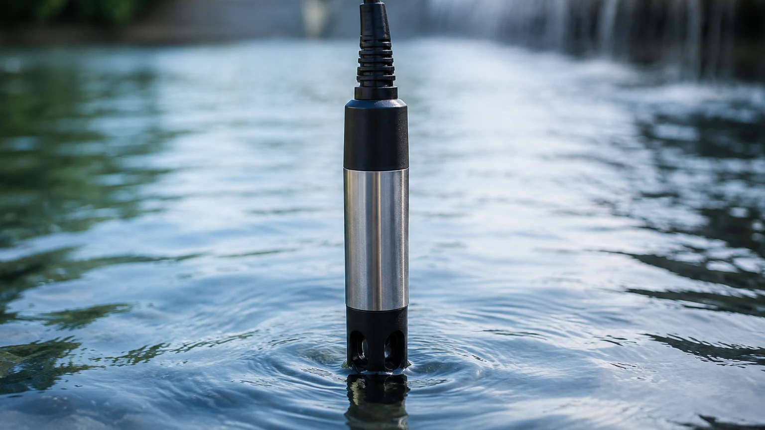
A robust industrial water turbidity sensor consists of several critical components that must withstand harsh process conditions:
1. Light Source: Modern sensors predominantly use Infrared (IR) LEDs with a wavelength of approximately 860 nm (following the ISO 7027 standard). IR light is preferred because it minimizes interference from the natural color of the water, which can absorb visible light and skew readings.
2. Optical Windows: These are typically made of sapphire or hardened glass. Sapphire is preferred in industrial settings due to its high resistance to scratching and chemical erosion.
3. Housing Material: For immersion in tanks or open channels, 316L stainless steel or PVC/CPVC housings are common. In highly corrosive chemical environments, titanium or specialized plastics may be required.
4. Signal Processing: Internal electronics convert the optical signal into a standardized industrial output, such as 4-20mA, Modbus RS485, or HART protocol, allowing for integration with PLCs and SCADA systems.
Practical Selection Criteria
Selecting the right water turbidity sensor requires an analysis of the specific process environment. Engineers should consult the Main Page of the manufacturer's catalog to review the full range of available optical and level measurement technologies before finalizing a specification.
Selection Table: Turbidity Sensor Types by Application
| Feature | Nephelometric (90°) | Transmission (180°) | Backscatter |
| :— | :— | :— | :— |
| Optimal Range | 0–100 NTU | 100–4,000 NTU | >4,000 NTU / Sludge |
| Primary Use | Drinking water, filtered water | Raw water, wastewater | Sludge density, industrial pulp |
| Sensitivity | High (detects fine particles) | Moderate | Low (focuses on density) |
| Interference Risk | Stray light | Color of the liquid | Particle size distribution |
| Typical Units | NTU, FNU | FAU, FTU | g/L, % TSS |
Installation Considerations and Best Practices
Proper installation is as important as sensor selection. Even the most accurate water turbidity sensor will provide erroneous data if placed incorrectly.
Avoiding Air Bubbles
Air bubbles are the primary enemy of optical turbidity measurement. A bubble scatters light much like a solid particle, leading to falsely high turbidity readings. In pressurized pipelines, bubbles are less common, but in open channels or gravity-fed systems, they are frequent.
* Solution: Use a "de-bubbler" or a flow cell with a stilling chamber to allow air to escape before the water reaches the sensor's optical path.
Flow Velocity and Orientation
The sensor should be installed in a location with constant flow to prevent particles from settling on the optical windows. However, excessively high velocity can cause cavitation or turbulence, which generates bubbles.
* Orientation: If installing in a horizontal pipe, the sensor should be mounted on the side (3 o'clock or 9 o'clock position). Mounting on the top can lead to interference from air pockets, while mounting on the bottom can lead to the sensor being buried in sediment.
Ambient Light Interference
External light sources (sunlight or overhead factory lighting) can penetrate the water and reach the sensor's detector, causing "stray light" errors.
* Solution: Use light-shielded flow cells or ensure that immersion sensors are placed deep enough or in shaded areas to eliminate ambient light interference.
Limitations and Common Risks
While highly effective, optical turbidity sensors have inherent limitations that must be managed through engineering design:
* Biofouling: In wastewater or untreated surface water, algae and bacterial films can grow on the sensor lens. This gradually drifts the measurement, usually upwards. Automated cleaning systems, such as mechanical wipers or ultrasonic cleaning heads, are essential for these applications.
* Particle Color and Shape: Turbidity is an optical measurement, not a mass measurement. Two samples with the same mass of suspended solids may yield different NTU readings if one sample has dark, jagged particles and the other has light, spherical particles. Calibration must be performed using the actual process fluid if mass concentration (mg/L) is the desired output.
* Scaling: In hard water or chemical processes, calcium carbonate or other minerals may scale on the lens. Chemical cleaning cycles or specialized coatings on the lens can mitigate this risk.
Maintenance and Calibration Procedures
To maintain accuracy, a regular maintenance schedule is required. Most industrial water turbidity sensors require verification every 3 to 6 months, depending on the cleanliness of the medium.
1. Manual Cleaning: Use a soft cloth and a mild detergent or dilute acid (if appropriate for the lens material) to remove stubborn deposits.
2. Zero Calibration: Use "turbidity-free" water (filtered through a 0.1 μm membrane) to set the zero point of the instrument.
3. Slope Calibration: Use a standardized Formazin solution or a stabilized synthetic standard (such as AMCO Clear) to calibrate the upper range. Formazin is the universal primary standard, but it is toxic and has a short shelf life, making synthetic standards more popular for field use.
Frequently Asked Questions (FAQs)
Q: What is the difference between NTU and FNU?
A: NTU (Nephelometric Turbidity Units) usually refers to measurements taken with a white light (tungsten) source according to EPA 180.1. FNU (Formazin Nephelometric Units) refers to measurements taken with an infrared light source according to ISO 7027. While they both measure 90-degree scatter, the light source difference means they may react differently to colored samples.
Q: Can a turbidity sensor measure Total Suspended Solids (TSS)?
A: Yes, but only through correlation. A turbidity sensor measures light scatter, while TSS is a gravimetric measurement (mg/L). By taking several laboratory TSS samples and comparing them to the sensor's NTU readings, a conversion factor can be programmed into the sensor's transmitter.
Q: How do I handle high-pressure applications?
A: Standard immersion sensors are often rated for low pressure. For high-pressure pipelines, a flow-through cell or a retractable probe with a ball valve assembly is required. This allows the sensor to be removed for maintenance without shutting down the entire process line.
Q: Is a wiper always necessary?
A: For drinking water or clean condensate return, a wiper is usually unnecessary. For any application involving raw surface water, wastewater, or biological processes, a wiper or an automated cleaning system is highly recommended to reduce manual maintenance labor.
By integrating these technical considerations into the system design, industrial operators can ensure that their water turbidity sensor provides reliable, long-term data for process optimization and regulatory compliance. For further technical specifications and to explore complementary level measurement instruments, users are encouraged to visit the Main Page for comprehensive product documentation.