Weir Flow Meter
Weir Flow Meter
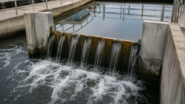
In industrial water management and civil engineering, measuring the flow of liquids in open channels is a critical requirement for process control, environmental compliance, and billing. One of the most established and reliable methods for achieving this is the use of a weir flow meter. A weir is essentially a man-made obstruction or dam placed across an open channel, designed to force the liquid to flow over a specifically shaped opening or notch.
By measuring the liquid level (the "head") upstream of the weir, engineers can calculate the volumetric flow rate using standardized hydraulic formulas. This article provides a technical overview of weir flow meter principles, types, selection criteria, and installation requirements to assist process engineers in implementing accurate measurement systems.
Measurement Principles of Weir Flow Meters
The operation of a weir flow meter is based on the principle of energy conservation in fluid mechanics, specifically the relationship between potential energy (liquid level) and kinetic energy (flow velocity). When a weir is placed in a channel, it creates a backwater effect, raising the liquid level upstream.
As the liquid passes over the crest of the weir, it accelerates. For a given weir geometry, there is a fixed mathematical relationship between the height of the liquid above the weir crest—known as the head ($H$)—and the flow rate ($Q$). The general discharge equation for a weir is expressed as:
$$Q = C \cdot L \cdot H^n$$
Where:
* $Q$ is the flow rate.
* $C$ is the discharge coefficient (determined by the weir shape and fluid properties).
* $L$ is the effective width of the weir crest.
* $H$ is the head (the vertical distance from the crest to the liquid surface).
* $n$ is an exponent that varies based on the shape of the notch (e.g., 1.5 for rectangular weirs, 2.5 for V-notch weirs).
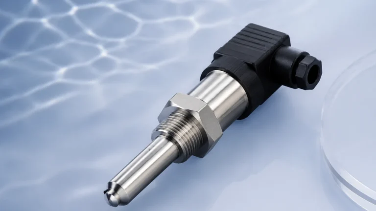
To automate this measurement, a level sensor—typically an ultrasonic or radar level meter—is installed at a specific distance upstream. The sensor measures the distance to the liquid surface, converts this into the head value, and the integrated electronics or a separate flow computer applies the relevant formula to output the real-time flow rate.
Types of Weir Flow Meters
Selecting the correct weir geometry is the most important factor in ensuring measurement sensitivity and rangeability. The three most common types used in industrial applications are the V-notch, rectangular, and Cipolletti weirs.
1. V-Notch (Triangular) Weirs
The V-notch weir features a triangular opening. It is the most accurate choice for measuring low flow rates because the cross-sectional area of the flow decreases rapidly as the head drops, maintaining a measurable head even at very low discharge volumes. Common notch angles include 22.5°, 30°, 45°, 60°, and 90°. The 90° V-notch is the industrial standard for general-purpose low-to-medium flow measurement.
2. Rectangular Weirs
Rectangular weirs are designed for higher flow capacities. They can be classified into two sub-types:
* Suppressed Rectangular Weirs: The weir crest extends across the entire width of the channel. There are no side contractions, meaning the liquid does not contract laterally as it passes over the crest.
* Contracted Rectangular Weirs: The weir opening is narrower than the channel width. This causes the flow to contract from the sides, which requires a specific correction factor in the flow calculation.
3. Cipolletti (Trapezoidal) Weirs
The Cipolletti weir is a trapezoidal weir with side slopes of 1 horizontal to 4 vertical. This specific geometry is designed to compensate for the effects of end contractions found in rectangular weirs. This simplifies the discharge calculation, as the flow rate is directly proportional to the length of the crest, making it a popular choice in irrigation and large-scale water distribution.
Technical Selection Table
When evaluating which weir flow meter to implement, engineers should consider the following performance characteristics:
| Weir Type | Flow Range | Accuracy | Sensitivity to Low Flow | Primary Application |
| :— | :— | :— | :— | :— |
| 90° V-Notch | Low to Medium | High (±2-3%) | Excellent | Laboratory, small effluent lines |
| Rectangular (Contracted) | Medium to High | Moderate (±3-5%) | Poor | Industrial discharge, storm water |
| Rectangular (Suppressed) | Very High | Moderate (±3-5%) | Very Poor | Large canals, river diversion |
| Cipolletti | Medium to High | Moderate (±3-5%) | Fair | Irrigation, water treatment plants |
Integration with Level Measurement Technology
A weir plate alone is only a primary element; the accuracy of the total weir flow meter system depends heavily on the secondary instrument—the level sensor. For industrial environments, Welk provides a range of advanced sensors designed to integrate seamlessly with weir structures. You can Review product options and application support on our Main Page to find the specific sensor technology that fits your installation environment.
* Ultrasonic Level Sensors: These are the most common choice for open channel flow. They are non-contact, cost-effective, and easy to install. However, they can be affected by heavy foam, steam, or extreme air temperature gradients.
* Radar Level Meters: For applications involving high temperatures, steam, or surface turbulence, radar sensors offer superior reliability. Since radar waves do not require air as a travel medium, they are unaffected by ambient conditions that might interfere with ultrasonic signals.
* Hydrostatic Pressure Transmitters: In cases where non-contact measurement is not feasible (e.g., very narrow manholes with internal obstructions), a submersible pressure transmitter can be used to measure the head by sensing the liquid column's weight.
Installation Considerations and Best Practices
The physical installation of a weir flow meter is often where errors are introduced. To maintain the validity of hydraulic formulas, the following engineering guidelines must be followed:
1. The Approach Channel
The channel upstream of the weir must be straight and free of obstructions for a distance of at least 10 to 20 times the maximum head ($H_{max}$). This ensures that the flow is laminar (smooth) and that the velocity distribution is uniform across the channel.
2. Point of Head Measurement
The level sensor must not be placed directly above the weir crest. As liquid approaches the weir, the surface curves downward (a phenomenon known as "drawdown"). To measure the true static head, the sensor should be located upstream at a distance of 3 to 4 times the maximum head ($H_{max}$).
3. Nappe Aeration
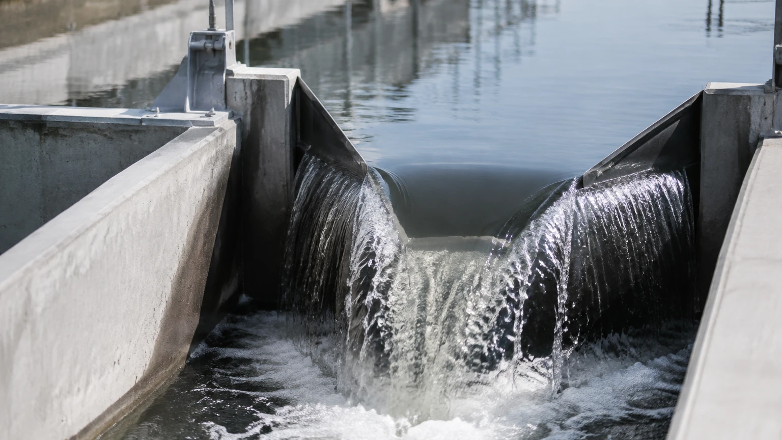
The "nappe" is the sheet of water flowing over the weir. For the discharge equations to remain accurate, air must circulate freely under the nappe. If a vacuum forms under the water sheet, the nappe will "cling" to the weir plate, increasing the flow rate for a given head and causing significant measurement errors. In suppressed rectangular weirs, aeration pipes are often required to prevent this.
4. Crest Condition
The crest of the weir must be sharp-edged (typically 1 mm to 2 mm thick) and kept clean. A rounded or rusted crest will change the discharge coefficient, leading to under-reporting or over-reporting of flow volumes.
Limitations and Common Risks
While weir flow meters are robust, they are not suitable for every application. Engineers should be aware of the following limitations:
* Head Loss: Weirs require a significant drop in the channel bed elevation. If the downstream water level rises too high (a condition known as submergence), the weir no longer functions according to standard formulas. The downstream level should always be at least 5 cm to 10 cm (0.05 m to 0.1 m) below the weir crest.
* Sediment Accumulation: Because a weir acts as a small dam, it naturally slows the water velocity upstream. This can cause silt, sand, and debris to settle at the base of the weir plate. Over time, this accumulation changes the channel hydraulics and must be removed through regular maintenance.
* Accuracy at Extremes: If the head is too low (less than 6 cm or 0.06 m), surface tension and fluid viscosity begin to dominate, making the standard formulas unreliable. Conversely, if the head is too high relative to the weir width, the measurement accuracy decreases.
Maintenance Checklist
To ensure long-term accuracy of a weir flow meter system, the following maintenance tasks should be performed quarterly:
1. Inspect the Crest: Ensure the weir edge is sharp, level, and free of nicks or debris.
2. Check for Leaks: Inspect the seals where the weir plate meets the channel walls to ensure no water is bypassing the notch.
3. Clear the Stilling Well: If a stilling well or approach channel is used, remove any accumulated sediment or biological growth.
4. Sensor Calibration: Verify the level sensor's "zero point" (the distance from the sensor to the crest level) using a manual gauge or staff gauge.
Frequently Asked Questions (FAQ)
Q: Can I use a weir flow meter for wastewater containing large solids?
A: It is generally not recommended. Solids tend to collect behind the weir plate or snag on the crest. For high-solids wastewater, a Parshall flume is typically a better choice as it is "self-cleaning."
Q: How do I handle "submerged" flow conditions?
A: If the downstream level rises above the crest, you must use a dual-sensor system to measure both upstream and downstream levels and apply a submergence correction factor. However, this significantly reduces accuracy. It is better to redesign the channel to ensure free-flow conditions.
Q: What is the advantage of using a radar sensor over an ultrasonic sensor for weir measurement?
A: Radar is immune to changes in air temperature and the presence of foam or steam, which can cause ultrasonic sensors to lose signal or provide false readings. Radar provides a higher degree of reliability in outdoor installations where sun loading can create temperature gradients in the air.
For technical assistance in selecting the right level instrumentation for your weir flow meter project, visit our Main Page to consult with our engineering team or explore our full range of radar and ultrasonic solutions.