What Is a Liquid Line
What Is a Liquid Line
In the context of industrial process engineering and fluid management, the term "liquid line" carries two primary meanings depending on the specific application: it can refer to the physical piping that transports a substance in its liquid phase, or it can refer to the interface level between a liquid and a gas within a storage vessel. For instrumentation engineers and plant operators, understanding what is a liquid line is essential for selecting the correct measurement technologies and ensuring the safety of pressurized systems.
From a level measurement perspective, identifying the liquid line is the fundamental goal of any level sensor. Whether the media is water, corrosive chemicals, or hydrocarbons, the ability to accurately locate this boundary ensures that tanks do not overfill and pumps do not run dry. This article explores the technical definitions of liquid lines, the principles used to measure them, and the practical considerations for selecting industrial instrumentation from a professional Main Page.
Technical Definitions of a Liquid Line
To provide a comprehensive answer to what is a liquid line, we must distinguish between its role in thermodynamics and its role in process automation.
1. The Physical Process Line
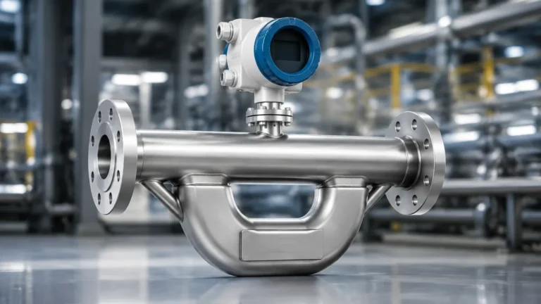
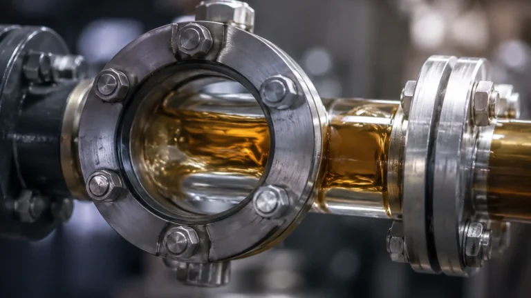
In refrigeration and HVAC systems, the liquid line is the segment of piping that connects the condenser to the expansion device. It carries high-pressure liquid refrigerant. In general chemical processing, a liquid line refers to any conduit where the fluid is maintained strictly in a liquid state, as opposed to a "suction line" or "vapor line" which carries gases.
2. The Liquid-Gas Interface
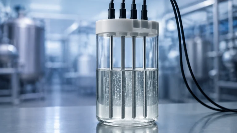
In level measurement, the liquid line is the surface of the liquid. It represents the transition point where the physical properties of the medium—such as density, dielectric constant, and acoustic impedance—change abruptly. Level meters are designed to detect this specific transition to calculate the volume or height of the material in a tank.
Measurement Principles for Detecting the Liquid Line
Before selecting an instrument, it is vital to understand the physics of how different sensors interact with the liquid surface. Industrial level measurement generally falls into three categories: reflectometry, pressure-based sensing, and displacement.
Time-of-Flight (ToF) Principles
Technologies such as Radar and Ultrasonic sensors rely on the Time-of-Flight principle. The sensor emits a signal (electromagnetic or acoustic) that travels through the vapor space, hits the liquid line, and reflects back to the receiver. By measuring the time taken for this round trip and knowing the speed of the signal, the device calculates the distance to the liquid surface.
Hydrostatic Pressure
This principle assumes that the pressure at the bottom of a vessel is directly proportional to the height of the liquid column above it. The sensor measures the weight of the liquid. If the density of the liquid is constant, the "liquid line" can be determined with high precision by converting the pressure (P) into height (h) using the formula $P = \rho gh$, where $\rho$ is density and $g$ is gravity.
Buoyancy and Displacement
Magnetic level gauges and float switches use the Archimedes principle. A float is designed to be less dense than the liquid but more dense than the gas above it, allowing it to sit precisely on the liquid line. As the level rises or falls, the float moves accordingly, often triggering a magnetic display or an electronic transmitter.
Key Technologies for Liquid Line Detection
Choosing the right technology requires matching the sensor's capabilities with the physical properties of the liquid and the environmental conditions of the tank.
Radar Level Meters
Radar is often considered the gold standard for detecting the liquid line in challenging environments.
- Non-contact Radar: Uses high-frequency signals (often 26GHz or 80GHz) to bounce off the surface. It is unaffected by temperature fluctuations, vacuum, or high pressure.
- Guided Wave Radar (GWR): Uses a physical probe to guide the microwave signal. This is particularly effective for liquids with low dielectric constants or in applications where the liquid surface is turbulent.
Ultrasonic Level Sensors
Ultrasonic sensors are a cost-effective solution for many water and wastewater applications. They work by emitting sound pulses. However, they are sensitive to the composition of the air in the vapor space. If there is heavy steam, dust, or significant temperature gradients, the speed of sound changes, which can lead to inaccuracies in locating the liquid line.
Hydrostatic Transmitters
For deep wells or tall, vented tanks, hydrostatic transmitters provide a reliable measurement of the liquid line. These are often submerged at the bottom of the tank or mounted to a flange at the base. They are highly effective for consistent liquids but require recalibration if the liquid density changes significantly.
Selection Criteria for Industrial Applications
When evaluating what is a liquid line measurement solution for your facility, use the following table to compare common technologies based on typical process parameters.
| Technology | Accuracy | Max Temperature | Max Pressure | Best Use Case |
| :— | :— | :— | :— | :— |
| Non-contact Radar | ±1 mm to ±5 mm | Up to +450°C | Up to 160 bar | Corrosive chemicals, high-temp reactors |
| Guided Wave Radar | ±2 mm | Up to +400°C | Up to 400 bar | Small tanks, low dielectric fluids, foam |
| Ultrasonic | ±0.25% of range | Up to +80°C | Up to 3 bar | Water treatment, open channels |
| Hydrostatic | ±0.1% to ±0.5% | Up to +120°C | N/A (Submersible) | Deep wells, fuel storage, vented tanks |
| Magnetic Gauge | ±5 mm to ±10 mm | Up to +400°C | Up to 250 bar | Visual monitoring, high-pressure boilers |
Installation Considerations and Best Practices
Even the most advanced sensor will fail to detect the liquid line correctly if installed improperly. Engineers must consider the internal geometry of the vessel.
1. Nozzle Positioning: For radar and ultrasonic sensors, the device should be mounted away from the tank wall to avoid false reflections (interference). Typically, the sensor should be placed at 1/6th to 1/4th of the tank diameter from the wall.
2. Obstruction Avoidance: Avoid installing sensors directly above agitators, heating coils, or inflow pipes. These obstructions can scatter the signal before it reaches the actual liquid line.
3. Stilling Wells and Bypass Chambers: In tanks with heavy turbulence or foam, a stilling well (a vertical pipe inside the tank) or an external bypass chamber can be used. This provides a "calm" liquid line for the sensor to measure, ensuring a stable and accurate reading.
4. Dead Zones: Every top-mounted sensor has a "dead zone" or "blocking distance" near the face of the transducer where measurement is impossible. Ensure the maximum liquid line never enters this zone to prevent signal loss.
Limitations and Environmental Challenges
Identifying the liquid line is not always straightforward. Several environmental factors can interfere with measurement accuracy:
* Foam: Heavy foam can absorb ultrasonic and radar signals, making the surface appear lower than it is or causing the signal to be lost entirely. Guided Wave Radar is usually the best solution for foamy applications.
* Vapor Layers: In high-pressure gas storage, a dense vapor layer can form above the liquid. This layer can refract radar signals or slow down ultrasonic pulses.
* Surface Turbulence: Rapid filling or agitation creates waves. This requires the use of software filtering (damping) in the transmitter to provide a steady average reading of the liquid line.
* Build-up: In sticky or viscous liquids, material can accumulate on the sensor face or probe. Non-contact radar is preferred here, as it does not touch the media.
Frequently Asked Questions (FAQ)
Q: Can a single sensor measure both the liquid line and an interface line?
A: Yes. Guided Wave Radar (GWR) is capable of measuring both the upper liquid line (e.g., oil) and the interface line where a second, denser liquid (e.g., water) begins, provided the top liquid has a lower dielectric constant.
Q: How does temperature affect the detection of the liquid line?
A: For ultrasonic sensors, temperature significantly changes the speed of sound, requiring integrated temperature compensation. For radar, temperature has a negligible effect on the signal speed, making it more stable in fluctuating environments.
Q: What is the difference between a liquid line and a suction line in piping?
A: In a closed-loop system like a chiller, the liquid line carries high-pressure liquid to the evaporator, while the suction line carries low-pressure gas back to the compressor. Level meters are typically installed on the receiver tanks located between these lines.
Conclusion
Defining what is a liquid line is the first step in designing an effective process control system. Whether you are monitoring the level in a simple water tank or a high-pressure chemical reactor, the choice of instrumentation depends on how the technology interacts with that liquid surface. By understanding the principles of radar, ultrasonic, and hydrostatic measurement, and by accounting for installation challenges like foam and turbulence, engineers can ensure long-term reliability and safety.
For those seeking specific hardware specifications or customized OEM solutions, visiting a specialized Main Page provides access to the technical data sheets and application support necessary to make an informed decision. Proper measurement of the liquid line is not just about data—it is about the efficiency and integrity of the entire industrial operation.