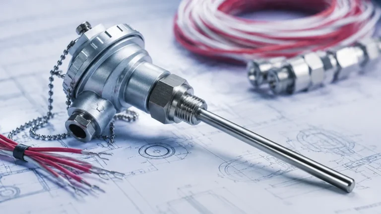
What Is Differential Pressure Transmitter
What Is Differential Pressure Transmitter
In the landscape of industrial automation and process control, the ability to measure fluid states accurately is fundamental to safety, efficiency, and quality. Among the various instruments used for this purpose, the differential pressure (DP) transmitter stands as one of the most versatile and widely utilized tools. Understanding what is differential pressure transmitter technology requires a look into the physics of pressure, the engineering of sensing elements, and the practical requirements of modern industrial facilities.
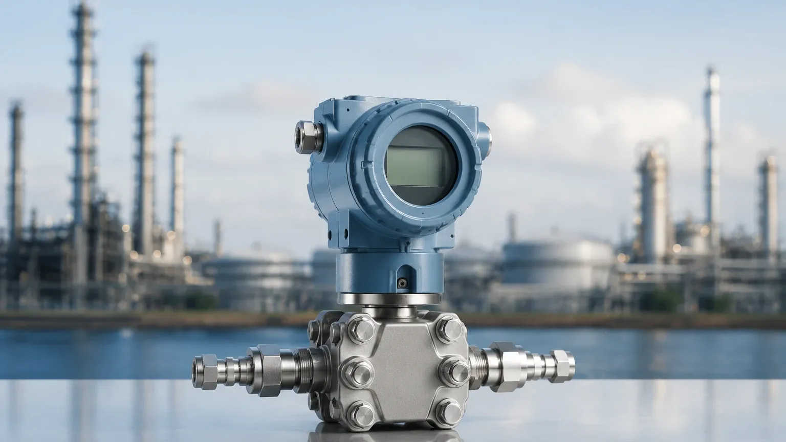
A differential pressure transmitter is a device designed to measure the difference in pressure between two distinct points in a process. Unlike a standard pressure gauge that measures pressure relative to a vacuum or the atmosphere, a DP transmitter focuses solely on the delta—the pressure drop or gain—between a high-pressure side and a low-pressure side. This measurement is then converted into an electrical signal, typically a 4-20mA current loop or a digital output via protocols like HART, Foundation Fieldbus, or Profibus, which can be interpreted by a control system.
Understanding the Core Measurement Principle
To answer the question of what is differential pressure transmitter functionality, we must examine how these devices interact with the process media. The core of the instrument is the sensing element, which is usually housed within a robust metal body.
The Sensing Element
Inside the transmitter, a sensing diaphragm is positioned between two pressure chambers. One chamber is connected to the "high-pressure" (H) side of the process, and the other to the "low-pressure" (L) side. As the process fluid exerts pressure on these diaphragms, the sensing element detects the physical displacement or the change in electrical properties caused by the imbalance.
There are several common technologies used for this detection:
* Capacitance Sensors: The sensing diaphragm acts as a movable electrode between two fixed capacitor plates. As the diaphragm shifts due to pressure differences, the capacitance changes. This change is highly linear and sensitive.
* Piezoresistive Sensors: Strain gauges are bonded to a silicon or metal diaphragm. The mechanical deformation of the diaphragm changes the electrical resistance of the gauges, which is then measured via a Wheatstone bridge circuit.
* Inductive Sensors: The movement of the diaphragm changes the inductance of a nearby coil, which is then processed into a signal.
Signal Conversion
Once the physical displacement is detected, the transmitter's internal electronics amplify and linearize the signal. In modern smart transmitters, microprocessors perform temperature compensation and scaling, ensuring that the output remains accurate even as environmental conditions fluctuate. For instance, if a transmitter is calibrated to measure a range of 0 to 100 kPa, it will output 4mA at 0 kPa and 20mA at 100 kPa.
Differential Pressure Transmitters in Level Measurement
While DP transmitters are frequently used to measure flow (by measuring the pressure drop across an orifice plate), one of their most critical roles is in liquid level measurement. This is particularly relevant for Welk’s range of industrial level measurement instruments.
Open Tank Measurement
In an open-to-atmosphere tank, the measurement is straightforward. The high-pressure side of the transmitter is connected to the bottom of the tank, while the low-pressure side is vented to the atmosphere. The pressure measured at the bottom is the hydrostatic head of the liquid.
The formula used is:
$$P = \rho \cdot g \cdot h$$
Where:
* $P$ is the hydrostatic pressure (measured by the transmitter).
* $\rho$ (rho) is the density of the liquid (kg/m³).
* $g$ is the gravitational constant (approx. 9.81 m/s²).
* $h$ is the height of the liquid (m).
By knowing the density of the fluid, the transmitter can accurately calculate the level based on the pressure exerted by the liquid column.
Closed and Pressurized Tank Measurement
In closed tanks, such as those found in chemical processing or oil and gas applications, the space above the liquid is often pressurized with a gas or vapor. A standard pressure transmitter would fail here because it cannot distinguish between the pressure of the gas and the pressure of the liquid.
This is where the DP transmitter is essential. The high-pressure side is connected to the bottom of the tank, and the low-pressure side is piped to the top of the tank (the vapor space). The transmitter subtracts the gas pressure from the total pressure at the bottom, leaving only the hydrostatic pressure of the liquid column. This allows for precise level measurement regardless of the internal tank pressure.
Technical Selection Guide
Choosing the right instrument requires a detailed understanding of the process environment. When engineers ask what is differential pressure transmitter suitability for their specific site, they must evaluate several technical parameters.
Selection Criteria Table
| Parameter | Consideration | Typical Options |
| :— | :— | :— |
| Pressure Range | The maximum and minimum expected differential. | 0.1 kPa to 40 MPa |
| Static Pressure | The total pressure the housing must withstand. | Up to 700 bar (70 MPa) |
| Wetted Materials | Compatibility with the process fluid to prevent corrosion. | SS316L, Hastelloy C, Tantalum, Monel |
| Accuracy | The required precision for the application. | ±0.075% to ±0.04% of span |
| Process Temperature | The temperature of the fluid at the sensing point. | -40°C to +120°C (higher with remote seals) |
| Output Protocol | Integration with existing control systems. | 4-20mA, HART, Modbus, Foundation Fieldbus |
Material Compatibility
For corrosive environments, such as those involving acids or seawater, the choice of diaphragm material is paramount. While Stainless Steel 316L is the standard, aggressive chemicals may require Hastelloy or Tantalum coatings. Furthermore, if the process fluid is prone to clogging or freezing in small impulse lines, a "Remote Seal" or "Diaphragm Seal" system is used. This uses a flexible capillary tube filled with silicone oil or other transmission fluids to transfer the pressure from the process to the transmitter body.
Installation Considerations and Best Practices
Correct installation is as important as the device selection itself. Even the most accurate transmitter will provide false data if installed improperly.
1. Impulse Piping: The small pipes connecting the process to the transmitter should be as short as possible to reduce lag and potential for leaks. For gas applications, the transmitter should be mounted above the tap points so condensate drains back into the process. For liquid applications, it should be mounted below the taps so gas bubbles can rise back into the tank.
2. Manifolds: A 3-valve or 5-valve manifold is almost always required. These allow the transmitter to be isolated from the process for maintenance and provide an equalization valve to zero the transmitter under static pressure conditions.
3. Mounting and Vibration: Transmitters should be mounted on a stable 2-inch pipe stand or wall bracket. Excessive vibration can fatigue the internal electronics and lead to premature failure.
4. Zeroing: After installation, the transmitter must be zeroed. This accounts for the weight of the fluid in the impulse lines (the "wet leg" or "dry leg" effect) and ensures the 4mA signal corresponds exactly to the zero-level state.
Limitations and Operational Risks
While DP transmitters are highly reliable, they are not without limitations.
* Density Sensitivity: Since the level measurement is derived from pressure, any change in the liquid's density (due to temperature changes or chemical composition shifts) will result in a level error. If the density decreases, the pressure drops, and the transmitter will report a lower level than what is physically present.
* Impulse Line Clogging: In applications with high solids content or viscous fluids, the impulse lines can plug. This "freezes" the reading, which can be dangerous in high-level alarm scenarios.
* Ambient Temperature Effects: Extreme cold can freeze the liquid inside impulse lines, while extreme heat can cause the fill fluid in remote seals to expand, creating a "temperature drift" in the reading.
Frequently Asked Questions (FAQ)
Q: Can a differential pressure transmitter measure flow?
A: Yes. By measuring the pressure drop across a primary flow element like an orifice plate, Venturi tube, or Pitot tube, the transmitter can calculate the flow rate. The flow rate is proportional to the square root of the differential pressure.
Q: What is the difference between a pressure transmitter and a differential pressure transmitter?
A: A standard pressure transmitter has one process connection and measures pressure relative to atmospheric pressure (gauge) or a vacuum (absolute). A DP transmitter has two connections and measures the difference between them.
Q: What is a "Wet Leg" in DP level measurement?
A: In closed tank applications where the vapor might condense into a liquid, the low-pressure impulse line is intentionally filled with a reference liquid. This is called a "wet leg." The weight of this liquid must be mathematically accounted for in the transmitter's calibration.
Q: How often should a DP transmitter be calibrated?
A: Most modern smart transmitters have excellent long-term stability (e.g., ±0.1% stability for 10 years). However, in critical safety or custody transfer applications, annual calibration or verification is standard practice.
Conclusion
Understanding what is differential pressure transmitter technology allows plant engineers to implement more robust control strategies. Whether it is monitoring the level of a pressurized chemical reactor or ensuring the steady flow of water in a treatment facility, these instruments provide the data necessary for automated decision-making. By carefully selecting materials, understanding the hydrostatic principles, and following strict installation guidelines, industrial operators can achieve high levels of accuracy and long-term reliability.
For those seeking specific hardware solutions, including radar, ultrasonic, and hydrostatic options, you can Review product options and application support on our Main Page to find the right fit for your industrial automation needs. Welk continues to provide advanced technology and customized OEM/ODM services to ensure that every level measurement challenge is met with a precise and cost-effective solution.