Guided Wave Radar Level Transmitter Emerson
Guided Wave Radar Level Transmitter Emerson: A Technical Engineering Guide
In the landscape of industrial process control, accurate level measurement is critical for safety, efficiency, and inventory management. Among the various technologies available, Guided Wave Radar (GWR) has emerged as a robust solution for challenging environments. This guide examines the engineering principles, selection criteria, and installation requirements for the guided wave radar level transmitter emerson series, providing a technical framework for engineers and procurement specialists.
Understanding Guided Wave Radar (GWR) Technology
Guided Wave Radar is a contact-based measurement method that utilizes Time Domain Reflectometry (TDR). Unlike non-contact radar, which broadcasts electromagnetic waves through the air, GWR directs these pulses along a physical probe or waveguide. This fundamental difference allows GWR to overcome many of the limitations faced by non-contact sensors, such as surface turbulence, foam, or dust.
Within the broader category of Radar Level Meters, GWR is often preferred for applications involving low dielectric constants, narrow tanks, or internal obstructions. By confining the signal to a probe, the energy loss is minimized, and the signal-to-noise ratio is significantly improved.
Measurement Principles: Time Domain Reflectometry (TDR)
The operation of a guided wave radar level transmitter emerson (such as the Rosemount 5300 or 3300 series) is based on the speed of light. The transmitter electronics generate a low-energy microwave pulse that travels down the probe at the speed of light. When this pulse reaches the surface of the medium being measured, a portion of the energy is reflected back to the transmitter.
The reflection occurs due to a change in the dielectric constant ($ε_r$) between the upper medium (usually air or gas, where $ε_r ≈ 1$) and the process medium. The transmitter measures the time-of-flight between the pulse emission and the reception of the echo. Since the speed of the pulse is constant, the distance to the surface is calculated as:
$$Distance = \frac{Speed \times Time}{2}$$
Interface Measurement Capabilities
One of the primary advantages of GWR technology is its ability to measure both the total level and the interface level between two liquids (e.g., oil and water). If the upper liquid has a low dielectric constant (typically < 10) and the lower liquid has a high dielectric constant, the microwave pulse will partially reflect off the first surface and continue through the upper liquid to reflect off the second interface.
Key Features of the Guided Wave Radar Level Transmitter Emerson Series
Emerson’s Rosemount series of GWR transmitters are engineered for high-reliability performance in demanding process conditions. Key technical features often include:
1. Direct Switch Technology: This enhances signal strength, allowing for longer probe lengths and measurement of media with very low dielectric constants (down to 1.2).
2. Signal Quality Metrics: Advanced diagnostics that monitor the health of the probe and the signal-to-noise ratio, providing predictive maintenance alerts before a failure occurs.
3. Probe End Projection: A feature used when the signal is lost due to extreme conditions; the transmitter uses the known probe length to calculate the level based on the propagation speed in the medium.
4. High Pressure/Temperature Housing: Designed to withstand pressures up to 345 bar (5000 psi) and temperatures up to 400°C, making them suitable for steam drums and chemical reactors.
Probe Selection and Material Compatibility
Selecting the correct probe is the most critical step in applying a guided wave radar level transmitter emerson. Probes are generally categorized into three types:
1. Single Lead Probes (Single Wire or Rod)
These are the most versatile and easiest to clean. They are less susceptible to media build-up but are more sensitive to the surrounding environment. They require a larger "keep-out" zone from tank walls and internal obstructions.
2. Twin Lead Probes (Twin Wire or Rod)
Twin probes provide a stronger signal than single leads and are better suited for longer ranges or lower dielectric fluids. However, they are highly susceptible to fouling and bridging between the leads, making them unsuitable for viscous or sticky liquids.
3. Coaxial Probes
Coaxial probes consist of a rod inside a perforated tube. The electromagnetic field is completely contained within the tube, offering the highest signal-to-noise ratio. They are unaffected by tank walls or foam. They are the gold standard for low dielectric liquids but should only be used with clean, low-viscosity fluids to prevent clogging.
| Feature | Single Lead | Twin Lead | Coaxial |
| :— | :— | :— | :— |
| Dielectric Range (ε_r) | > 2.0 | > 1.9 | > 1.2 |
| Max Viscosity | High (Up to 10,000 cP) | Medium (< 500 cP) | Low (< 500 cP) |
| Foam Resistance | Moderate | Good | Excellent |
| Build-up Sensitivity | Low | High | Very High |
| Internal Obstructions | Sensitive | Less Sensitive | Immune |
Installation Constraints and Engineering Best Practices
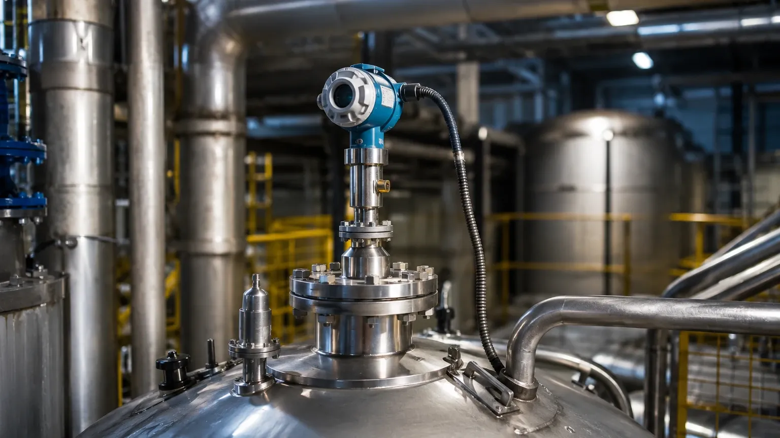
To ensure the accuracy of Radar Level Meters, engineers must adhere to specific installation guidelines. For GWR transmitters, the following factors are paramount:
* Nozzle Geometry: The nozzle diameter and height can affect the signal near the top of the tank. For single lead probes, the nozzle should be as wide and short as possible to minimize parasitic reflections.
* Obstructions: Maintain a minimum clearance (usually 100mm to 300mm) from agitators, ladders, and heating coils. If the probe touches a metal object, it will create a false reflection.
* Stilling Wells and Bypasses: In turbulent tanks or tanks with heavy foam, GWR probes are often installed in stilling wells or external bypass chambers. This provides a calm surface for measurement and can simplify maintenance without breaking tank vacuum or pressure.
* Probe Centering: In coaxial or twin-lead applications, ensuring the probe remains vertical and centered is vital to prevent short-circuiting the signal against the pipe wall.
Application Risks and Technical Limitations
While highly capable, the guided wave radar level transmitter emerson is not a universal solution. Engineers must account for the following risks:
1. Probe Build-up: Conductive coating or bridging on the probe can cause signal attenuation or "virtual levels." If the medium is prone to crystallization or heavy coating, a non-contact radar may be more appropriate.
2. Dielectric Shifts: If the dielectric constant of the upper medium changes significantly (e.g., changing from air to a high-pressure vapor), the propagation speed of the pulse changes, leading to measurement errors. High-end GWR units include Dynamic Vapor Compensation (DVC) to correct for this.
3. Mechanical Stress: In high-flow applications or tanks with heavy agitation, the lateral forces on a long probe can cause bending or breakage. Support brackets or heavier rod diameters may be required.
Selection Table for Industrial GWR Transmitters
When specifying a transmitter, use the following table to align process requirements with equipment capabilities:
| Process Variable | Requirement | Recommended Specification |
| :— | :— | :— |
| Medium State | Liquid or Solid | Rod for liquids; Cable for solids |
| Dielectric (ε_r) | < 1.4 | Coaxial Probe |
| Temperature | > 250°C | High-temperature ceramic seal |
| Pressure | > 40 bar | Dual-seal process connection |
| Interface | Oil/Water | GWR with Interface software |
| Tank Height | > 10 meters | Flexible cable probe |
Frequently Asked Questions (FAQ)
Q: Can GWR measure levels in plastic tanks?
A: Yes. Unlike non-contact radar, which may require a metal launch plate, GWR is contained by the probe. However, for single lead probes, a metal flange or mounting plate is still recommended to provide a proper reference ground for the signal.
Q: How does foam affect GWR measurement?
A: Generally, GWR performs well in foam. Depending on the foam's density and dielectric, the signal may reflect off the top of the foam, pass through it to the liquid, or be absorbed. Coaxial probes are the most effective at penetrating thick foam layers.
Q: Is it possible to shorten a GWR probe in the field?
A: Many GWR probes, particularly cable and single rod types, are designed to be field-cut. After cutting, the transmitter's configuration must be updated with the new probe length to maintain accuracy.
Q: What is the minimum dielectric constant required?
A: With advanced signal processing found in the guided wave radar level transmitter emerson, media with dielectrics as low as 1.2 can be measured, provided a coaxial probe is used to maximize signal return.
Conclusion
The implementation of a guided wave radar level transmitter emerson provides a high-precision solution for complex level and interface challenges. By understanding the underlying TDR principles and carefully selecting probe types based on media characteristics, industrial facilities can achieve reliable measurement even in extreme pressure and temperature conditions. For further technical specifications and to compare different radar technologies, engineers should consult comprehensive resources on Radar Level Meters to ensure the selected instrument matches the specific hydraulic and chemical demands of their process.
Download Guided Wave Radar Level Transmitter Emerson as a PDF