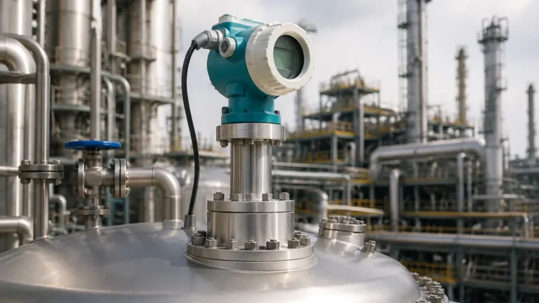
80 GHz Non Contact Radar Level Transmitter
80 GHz Non Contact Radar Level Transmitter
In the field of industrial process automation, precise level measurement is a fundamental requirement for inventory management, process safety, and efficiency. The emergence of the 80 GHz non contact radar level transmitter represents a significant technological shift in the instrumentation landscape. By utilizing higher frequencies compared to traditional 6 GHz or 26 GHz systems, these transmitters offer narrower beam angles and higher resolution, making them suitable for complex environments where previous radar technologies struggled.
This article provides a technical overview of 80 GHz radar technology, its operating principles, selection criteria, and practical installation considerations for engineering professionals.
Measurement Principle: FMCW Technology
Modern 80 GHz Radar Level Meters primarily operate on the Frequency Modulated Continuous Wave (FMCW) principle. Unlike pulse radar, which measures the time-of-flight of a single microwave pulse, FMCW transmitters emit a continuous signal with a frequency that increases linearly over time (a frequency sweep or "chirp").
The signal is reflected by the surface of the medium and received by the antenna. Because the transmitter is constantly changing the frequency of the emitted signal, there is a frequency difference between the emitted signal and the reflected signal at any given moment. This frequency difference ($Δf$) is directly proportional to the distance ($D$) between the sensor and the product surface.
The Advantage of 80 GHz Bandwidth
The resolution and accuracy of an FMCW radar are determined by the sweep bandwidth. A 26 GHz radar typically has a bandwidth of around 1-2 GHz. In contrast, an 80 GHz transmitter can utilize a bandwidth of up to 4 GHz. This wider bandwidth allows the device to distinguish between the actual product level and nearby interference (such as tank walls or agitators) with much higher precision. The range resolution of an 80 GHz system can be as fine as 1 mm (0.04 inches), providing a significant advantage in small tanks or high-accuracy applications.
Key Advantages of 80 GHz Systems
1. Narrow Beam Angle
The beam angle of a radar transmitter is inversely proportional to the frequency and the antenna diameter. At 80 GHz, the wavelength is approximately 3.75 mm. This short wavelength allows for a very narrow beam angle—often as small as 3° to 4°—even with a small process connection (e.g., 1-inch or 2-inch nozzles).
A narrow beam is critical in vessels with internal obstructions like heating coils, ladders, or agitators. It ensures that the microwave energy is focused on the liquid surface rather than reflecting off the tank walls or internal structures, which simplifies commissioning and reduces the need for complex false-signal suppression.
2. Enhanced Signal Sensitivity
80 GHz technology offers a higher dynamic range, meaning it can detect weaker return signals. This is particularly beneficial when measuring media with a low dielectric constant ($ε_r$), such as hydrocarbons, solvents, or plastic pellets. The higher frequency also results in better reflection from turbulent surfaces or foam, where lower-frequency signals might be scattered or absorbed.
3. Small Process Connections
Because the antenna size required to achieve a narrow beam is much smaller at 80 GHz, these transmitters can be installed on small nozzles. This makes them ideal for retrofitting into existing tanks where large flange openings are not available.
Technical Selection and Comparison
When selecting between various radar frequencies, engineers must evaluate the specific process conditions. The following table compares the typical characteristics of 26 GHz and 80 GHz non contact radar level transmitters.
| Feature | 26 GHz Radar | 80 GHz Radar |
| :— | :— | :— |
| Beam Angle (3" Antenna) | ~10° | ~3° |
| Accuracy | ±2 mm to ±5 mm | ±1 mm |
| Measuring Range | Up to 30 m (98 ft) | Up to 120 m (393 ft) |
| Smallest Nozzle Size | Typically 2" or larger | 1" or larger |
| Solids Performance | Good for large grains | Excellent for fine powders/dust |
| Sensitivity to Build-up | Moderate | High (requires lens antenna design) |
| Internal Obstructions | High interference risk | Low interference risk |
Installation Requirements and Best Practices
To ensure the reliability of an 80 GHz non contact radar level transmitter, several installation factors must be addressed during the engineering phase.
Nozzle Considerations
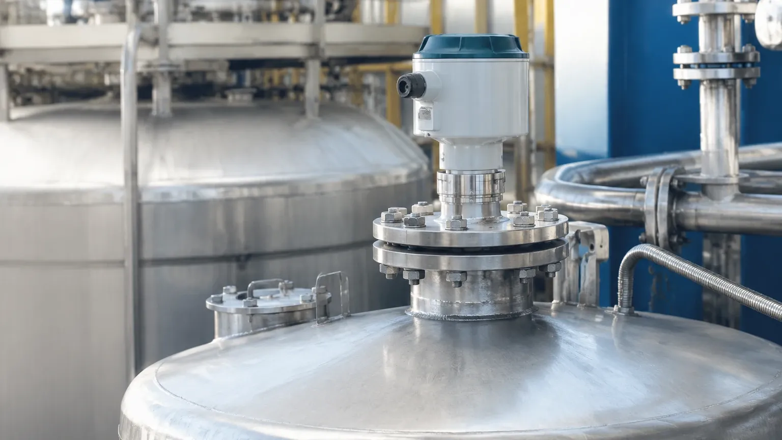
While 80 GHz radars are less sensitive to nozzle interference, the nozzle height should still be minimized. The antenna should ideally extend slightly beyond the bottom of the nozzle to prevent internal reflections. However, many modern 80 GHz units feature a lens antenna that is flush-mounted, which allows for installation in nozzles that are longer than the antenna itself without significant signal degradation.
Dead Zone (Blind Zone)
Every radar transmitter has a "dead zone" directly beneath the antenna where measurements are not possible. For 80 GHz units, this zone is typically very small (often less than 50 mm or 2 inches), but it must be accounted for when calculating the maximum fill level of the tank to prevent the medium from coming into contact with the antenna.
Orientation and Positioning
* Wall Distance: The transmitter should be installed at a distance from the tank wall that is at least 1/6th of the tank diameter to avoid multipath reflections.
* Avoid the Center: Do not install the transmitter in the exact center of a domed-roof tank, as this can concentrate parasitic reflections and weaken the signal-to-noise ratio.
* Agitators: If the tank has an agitator, the transmitter should be positioned so the beam path does not intersect the path of the blades, although the narrow 80 GHz beam makes this much easier to achieve than with lower-frequency models.
Limitations and Process Risks
Despite the advantages, 80 GHz technology is not a universal solution. Engineers should be aware of the following limitations:
1. Heavy Foam: While 80 GHz performs better than 26 GHz in many cases, extremely thick, dense foam can still absorb the microwave signal. In such instances, a guided wave radar (GWR) or a lower-frequency radar might be required to penetrate the foam layer.
2. Condensation and Build-up: High-frequency signals have shorter wavelengths, making them more susceptible to attenuation by water droplets or material build-up on the antenna. For applications with heavy condensation, a transmitter with a PTFE or PEEK lens antenna and a self-cleaning design (or an air purge connection) is recommended.
3. Dielectric Constant ($ε_r$): If the medium has an extremely low dielectric constant (below 1.4), the reflected signal may be too weak for reliable measurement. In these cases, a stilling well or a bypass pipe can be used to concentrate the signal energy.
Buyer’s Checklist for International Procurement
When sourcing an 80 GHz non contact radar level transmitter for industrial projects, international buyers should confirm the following technical specifications with the manufacturer:
* Process Temperature and Pressure: Confirm the transmitter can withstand the maximum and minimum process conditions. Standard units often handle up to 150°C (302°F) and 20 bar (290 psi), but high-temperature versions are available.
* Material Compatibility: Ensure the wetted parts (antenna material and seals) are compatible with the process medium (e.g., 316L Stainless Steel, PTFE, FKM).
* Output Protocol: Determine if the system requires 4-20mA HART, Modbus RTU, Profibus PA, or Foundation Fieldbus for integration into the DCS/PLC.
* Hazardous Area Certifications: Verify if ATEX, IECEx, or local certifications (like FM or CSA) are required for explosive atmospheres.
* Beam Angle and Range: Specify the required measuring range (e.g., 0-30m or 0-120m) and confirm the beam angle is narrow enough for the specific tank geometry.
Frequently Asked Questions
Q: Can 80 GHz radar measure solids and liquids?
A: Yes. 80 GHz is particularly effective for solids because the narrow beam and high frequency allow it to receive reflections from angled surfaces (the "angle of repose") and penetrate heavy dust during filling cycles.
Q: Is 80 GHz radar safe for food and beverage applications?
A: Yes, many 80 GHz transmitters are available with hygienic connections (Tri-Clamp) and FDA-approved materials like PTFE, making them suitable for CIP (Clean-in-Place) processes.
Q: Does the 80 GHz signal pass through plastic tank walls?
A: To some extent, yes. Because of the high frequency, it is possible to measure the level through the top of a plastic (PE/PP) tank without a process opening, provided the tank material is not conductive and the wall thickness is not excessive.
Conclusion
The 80 GHz non contact radar level transmitter has become the preferred choice for many industrial level measurement challenges. Its ability to provide high-precision data in narrow vessels, its immunity to most internal obstructions, and its suitability for both liquid and solid media make it a versatile tool for the modern engineer. By understanding the FMCW principle and adhering to proper installation guidelines, facilities can achieve reliable, maintenance-free level monitoring in even the most demanding process environments. For more information on specific configurations, professionals should consult technical documentation regarding Radar Level Meters to match the instrument to their specific application needs.
Download 80 GHz Non Contact Radar Level Transmitter as a PDF