Guided Wave Radar Level Transmitter vs Ultrasonic
Guided Wave Radar Level Transmitter vs Ultrasonic: A Technical Engineering Guide
In the landscape of industrial process automation, selecting the correct level measurement technology is critical for operational safety, inventory accuracy, and process efficiency. Two of the most prevalent technologies used for continuous level monitoring are Guided Wave Radar (GWR) and Ultrasonic sensors. While both function on the "Time of Flight" (ToF) principle, their physical interactions with the process environment differ significantly.
This guide provides a detailed technical comparison of the guided wave radar level transmitter vs ultrasonic sensors, examining their operating principles, performance under varying process conditions, and practical installation requirements for B2B industrial applications.
Understanding the Measurement Principles
Before evaluating which technology is superior for a specific application, it is essential to understand the physics governing each instrument.
Ultrasonic Level Measurement Principle
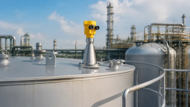
Ultrasonic sensors are non-contact instruments. The transducer emits a high-frequency acoustic pulse (usually between 20 kHz and 200 kHz) that travels through the air or gas space above the medium. When the sound wave hits the surface of the material, it is reflected back to the transducer.
The instrument measures the time interval between the emission of the pulse and the reception of the echo. Since the speed of sound in air is approximately 343 meters per second (at 20°C), the distance is calculated as:
Distance = (Speed of Sound × Time of Flight) / 2
Because the speed of sound is highly dependent on the temperature and composition of the gas through which it travels, most ultrasonic transmitters include an integrated temperature sensor to compensate for these changes.
Guided Wave Radar (GWR) Principle
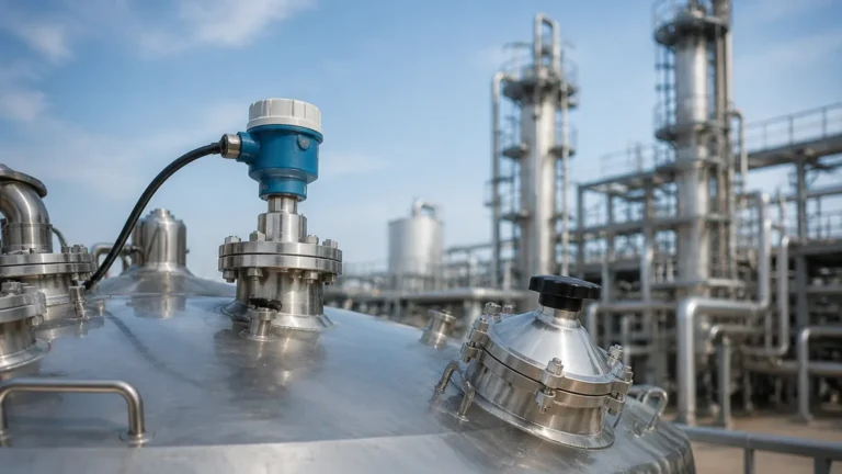
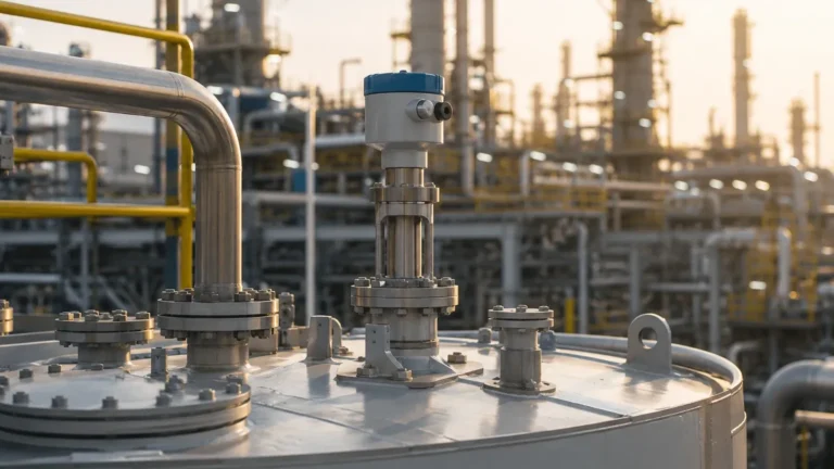
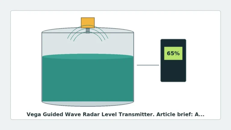
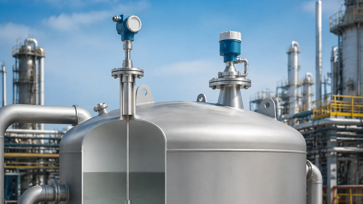
Guided Wave Radar is a contact-based technology that utilizes Time Domain Reflectometry (TDR). The transmitter generates low-power microwave pulses (electromagnetic waves) that are guided down a physical probe (rod, cable, or coaxial tube). When these pulses reach the surface of the medium, the change in the dielectric constant ($ε_r$) between the air/gas and the process medium causes a reflection.
Like ultrasonic sensors, GWR measures the time of flight. However, microwaves travel at the speed of light. Because electromagnetic waves do not require a medium for propagation and are largely unaffected by the physical properties of the gas space, GWR provides a more stable measurement in complex environments. For high-precision requirements, Radar Level Meters offer significant advantages in stability over acoustic-based systems.
Comparative Analysis: Guided Wave Radar vs Ultrasonic
Choosing between these two technologies requires an analysis of the process environment. The following factors are the primary drivers for selection in B2B engineering projects.
1. Influence of Gas Space Conditions
* Ultrasonic: Since sound requires a medium to travel, any change in the gas space affects the measurement. High levels of dust, heavy vapors, or steam can attenuate the sound signal, leading to signal loss. Furthermore, if the tank is under vacuum, ultrasonic waves cannot propagate at all.
* GWR: Microwaves are electromagnetic. They travel effectively through vacuums and are unaffected by steam, dust, or heavy vapor layers. This makes GWR the preferred choice for chemical reactors and high-temperature storage tanks.
2. Surface Turbulence and Foam
* Ultrasonic: Turbulent surfaces scatter sound waves, often resulting in erratic readings. Foam is a significant challenge; acoustic waves are usually absorbed by the foam or reflect off the top of the foam layer rather than the liquid level.
* GWR: Because the pulse is guided by a probe, it is less susceptible to signal scattering caused by turbulence. Regarding foam, GWR can often penetrate light foam to detect the liquid surface, or if the foam is dense and has a high dielectric constant, it will detect the top of the foam. This predictability is a major advantage in industrial mixing tanks.
3. Temperature and Pressure Limits
* Ultrasonic: Generally limited to temperatures below 80°C (176°F) and pressures below 0.3 MPa (approx. 3 bar). High temperatures create temperature gradients in the gas space that are difficult to compensate for accurately.
* GWR: Designed for extreme environments. Standard GWR units can handle temperatures from -200°C to +450°C and pressures up to 40 MPa (400 bar), making them suitable for high-pressure boilers and cryogenic storage.
4. Media Properties (Dielectric Constant)
* Ultrasonic: Measurement is independent of the dielectric constant. It only requires a solid or liquid surface capable of reflecting sound.
* GWR: Performance depends on the dielectric constant ($ε_r$) of the medium. Materials with high dielectrics (e.g., water, $ε_r ≈ 80$) produce very strong reflections. Low dielectric materials (e.g., oils, $ε_r < 2$) produce weak reflections, requiring specialized probe configurations like coaxial probes to concentrate the signal.
Selection Table for Industrial Applications
| Feature | Ultrasonic Level Sensors | Guided Wave Radar (GWR) |
| :— | :— | :— |
| Measurement Type | Non-contact (Acoustic) | Contact (Electromagnetic/TDR) |
| Medium Complexity | Simple liquids/solids | Complex liquids, solids, interfaces |
| Vacuum Compatibility | No (Requires air/gas) | Yes |
| Effect of Steam/Vapor | High (Signal attenuation) | Minimal to None |
| Max Temperature | ~80°C | ~450°C |
| Max Pressure | ~0.3 MPa | Up to 40 MPa |
| Accuracy | +/- 0.25% of range | +/- 2mm to 5mm |
| Maintenance | Low (No contact) | Low (No moving parts) |
| Cost | Generally Lower | Generally Higher |
Installation Considerations and Constraints
Success in level measurement is often determined by installation quality rather than the instrument itself. Engineers must account for the following:
Dead Zones (Blocking Distance)
Both technologies have a "dead zone" at the top of the sensor (near the flange or transducer face) where measurement is not possible.
* For Ultrasonic, this is typically 0.2m to 0.5m, depending on the frequency.
* For GWR, the upper dead zone is usually smaller (approx. 0.1m), but there is also a lower dead zone at the end of the probe where the signal loses linearity.
Tank Geometry and Obstructions
* Ultrasonic beams spread out in a cone (typically 5° to 12°). If this cone hits a ladder, pipe, or agitator, it will create a false echo.
* GWR concentrates the energy along the probe. While it still has a detection radius (the "electromagnetic field"), it is much narrower than an ultrasonic beam. This allows GWR to be installed in narrow nozzles or tanks with internal obstructions that would interfere with ultrasonic signals.
Probe Selection for GWR
When specifying a guided wave radar level transmitter, the probe type must match the media:
1. Single Rod/Cable: Best for liquids and applications where coating or buildup is a concern.
2. Twin Rod/Cable: Used for long-range measurements of low dielectric liquids.
3. Coaxial Probe: Provides the highest signal-to-noise ratio. Ideal for low dielectric fluids and tanks with many internal obstructions, as the signal is completely contained within the outer tube.
Limitations and Application Risks
While GWR is often seen as the more robust solution, it is not universal.
GWR Limitations:
* Mechanical Stress: In tall silos with heavy solids (like grain or cement), the pull-down forces on a GWR cable can be several tons, potentially damaging the tank roof or the sensor itself.
* Coating/Buildup: While GWR is resistant to thin coatings, heavy, conductive buildup between a twin-rod probe or inside a coaxial probe can cause signal bridging and false readings.
Ultrasonic Limitations:
* Wind/Air Movement: In outdoor open-channel flow applications, strong winds can "blow" the acoustic signal away from the receiver.
* Acoustic Noise: Heavy machinery or pneumatic filling can create ultrasonic noise that interferes with the sensor's frequency.
Frequently Asked Questions (FAQs)
Q: Can GWR measure the interface between two liquids?
A: Yes. This is a primary advantage of GWR. If the upper liquid has a lower dielectric constant (e.g., oil) and the lower liquid has a higher dielectric (e.g., water), the microwave pulse will reflect off both surfaces, allowing the transmitter to report both the total level and the interface level.
Q: Is ultrasonic better for corrosive acids?
A: Because ultrasonic is non-contact, the sensor body can be made of PVDF or PTFE, making it highly resistant to corrosion without the need for expensive alloy probes required by GWR.
Q: How does dust affect the choice?
A: For heavy dust environments (e.g., cement silos), ultrasonic usually fails because the dust absorbs the sound waves. GWR or high-frequency non-contact Radar Level Meters are significantly more reliable in these conditions.
Conclusion for International Procurement
When choosing between a guided wave radar level transmitter vs ultrasonic, the decision should be driven by the process physics.
* Select Ultrasonic for simple, atmospheric water treatment applications, open sumps, or corrosive chemical storage where the temperature is stable and the budget is a primary constraint.
* Select Guided Wave Radar for process vessels, high-pressure tanks, applications with steam/vapor, or when measuring interfaces between liquids.
For B2B buyers and engineers, confirming the dielectric constant of the medium, the presence of foam, and the potential for vacuum conditions during the RFQ (Request for Quote) stage will ensure the selected instrument provides reliable service throughout its operational lifecycle.
Download Guided Wave Radar Level Transmitter vs Ultrasonic as a PDF