Radar Level Transmitter on Tank
Radar Level Transmitter on Tank: A Technical Engineering Guide
In modern industrial process control, the accurate measurement of liquid and solid levels within storage and process vessels is critical for inventory management, safety, and operational efficiency. Among the various technologies available, the installation of a radar level transmitter on tank systems has become the preferred choice for engineers due to its non-contact nature and high reliability in challenging environments.
This guide explores the measurement principles, selection criteria, and installation best practices for Radar Level Meters to ensure optimal performance in B2B industrial applications.
1. Understanding Radar Measurement Principles
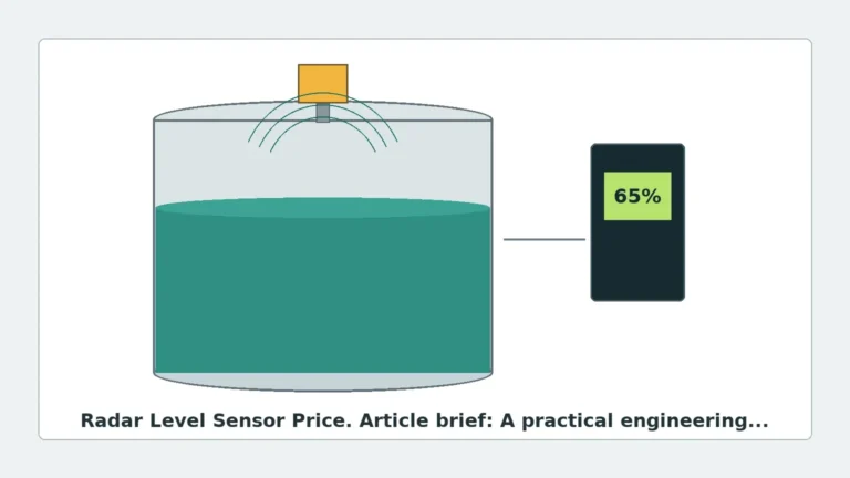
Before selecting a radar level transmitter, it is essential to understand how these devices interact with the medium and the tank environment. Radar level measurement is based on the travel time of microwaves, which move at the speed of light. There are two primary techniques used in industrial radar transmitters: Pulse Radar and Frequency Modulated Continuous Wave (FMCW).
Pulse Radar (Time of Flight)
Pulse radar transmitters emit short microwave pulses toward the product surface. The device measures the time interval between the emission of the pulse and the reception of the reflected echo. Since the speed of light is constant, the distance is calculated as:
\[ Distance = \frac{C \times t}{2} \]
*(Where C is the speed of light and t is the measured time)*
Pulse radar is often used in simpler applications where extreme precision is not the primary requirement, or where power consumption must be kept to a minimum.
FMCW (Frequency Modulated Continuous Wave)
FMCW radar emits a continuous high-frequency signal, but the frequency of that signal changes linearly over time (a frequency sweep). When the signal reflects off the material surface and returns to the antenna, it is compared against the frequency being emitted at that exact moment. The difference in frequency (the "beat frequency") is directly proportional to the distance.
FMCW technology, particularly at higher frequencies like 80GHz, offers superior signal-to-noise ratios and better resolution, making it ideal for tanks with internal obstructions or low-dielectric media.
2. Types of Radar Level Transmitters
When planning a radar level transmitter on tank installation, engineers must choose between non-contacting radar and guided wave radar (GWR).
Non-Contacting Radar
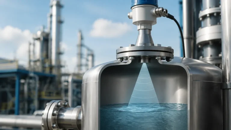
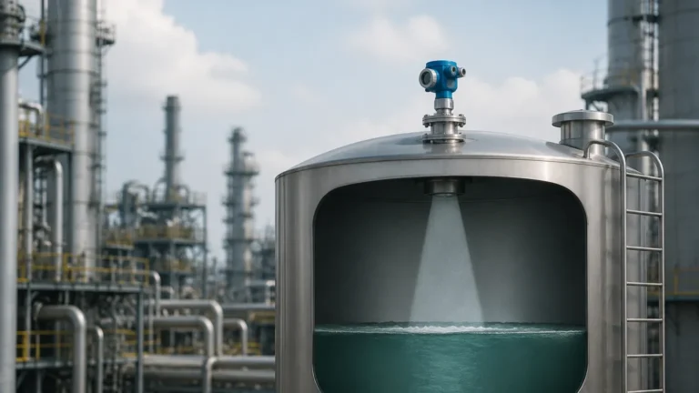
These devices are mounted at the top of the tank and emit signals through the air. They are ideal for corrosive, hygienic, or extremely hot materials because no part of the instrument (other than the antenna face) touches the medium.
* High-Frequency (80GHz): Offers a narrow beam angle, which is excellent for tall, narrow tanks or tanks with many internal structures.
* Mid-Frequency (26GHz): A versatile choice for most standard industrial liquids and solids.
Guided Wave Radar (GWR)
GWR uses a physical probe (a rod or cable) to guide the microwave signal to the surface. This technology is highly effective for media with low dielectric constants or in applications where heavy foam or turbulence is present, as the probe concentrates the signal energy.
3. Selection Criteria for Tank Applications
Choosing the right instrument requires a detailed analysis of the process conditions. The following table provides a general comparison for selection:
| Feature | 80GHz Non-Contact Radar | 26GHz Non-Contact Radar | Guided Wave Radar (GWR) |
| :— | :— | :— | :— |
| Beam Angle | Narrow (approx. 3° to 8°) | Medium (approx. 10° to 20°) | N/A (Signal follows probe) |
| Max Range | Up to 120m | Up to 30m – 70m | Up to 30m (Cable) |
| Accuracy | ±1 mm | ±2 mm to ±5 mm | ±2 mm |
| Foam Resistance | Moderate | Low | High |
| Internal Obstructions | Excellent avoidance | Moderate avoidance | Not affected (if probe clears) |
| Dielectric ($ε_r$) | ε_r > 1.4 | ε_r > 1.9 | ε_r > 1.2 |
Key Factors to Confirm:
1. Dielectric Constant (ε_r): This is the measure of a material's ability to reflect radar waves. Water has a high ε_r (~80), while hydrocarbons like oil have a low ε_r (~2.0). Lower dielectric materials require more sensitive electronics or GWR.
2. Process Temperature and Pressure: Standard radar units handle up to 150°C (302°F), but specialized high-temperature versions can withstand 450°C (842°F) or higher. Pressure ratings must match the tank's design pressure, often ranging from vacuum to 40 bar (580 psi) or more.
3. Tank Geometry: The height, diameter, and shape of the tank bottom (conical, flat, or dished) influence the choice of antenna and frequency.
4. Installation Considerations for Radar Level Transmitter on Tank
Correct physical placement is the most significant factor in the success of a radar level transmitter on tank project. Improper installation leads to false echoes and signal loss.
Positioning and Clearance
* Wall Distance: The transmitter should not be mounted too close to the tank wall. A general rule is to maintain a distance of at least 1/6th of the tank diameter from the wall to prevent interference from wall reflections.
* Avoid the Center: In tanks with a concave or dished bottom, do not mount the sensor in the exact center. The center point can act as a focal point for multiple reflections, causing "ghost" signals when the tank is near empty.
* Inflow Streams: Never install the radar unit directly above the fill pipe or inflow stream. The turbulence and the falling product will disrupt the signal.
Nozzle Requirements
The nozzle (the pipe segment on which the radar is mounted) must be designed correctly:
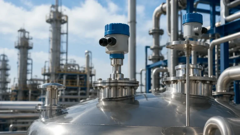
* Nozzle Length: The antenna should ideally extend slightly beyond the bottom of the nozzle to prevent signal ringing within the pipe. If using a horn antenna, ensure the horn diameter is smaller than the nozzle ID.
* Nozzle Diameter: Standard sizes are DN50, DN80, or DN100. Larger nozzles generally allow for antennas with narrower beam angles.
Internal Obstructions
Agitators, heating coils, ladders, and baffles can create false echoes. While modern software can "map out" these static obstructions, it is best to position the radar beam in a clear path to the product surface. If an agitator is present, the software must be configured to filter out intermittent signals caused by the moving blades.

5. Limitations and Application Risks
While radar is highly versatile, certain conditions pose risks to measurement accuracy:
* Heavy Foam: Thick, dense foam can absorb radar signals rather than reflecting them. In cases of persistent heavy foam, Guided Wave Radar is usually the more reliable solution.
* Condensation and Buildup: In high-humidity tanks, condensation can form on the antenna. While many Radar Level Meters feature PTFE drip-off lenses, heavy buildup of viscous or crystallizing media may eventually block the signal, requiring periodic cleaning or an air purge system.
* Dust and Solids: For silos containing powders or grains, the angle of repose (the slope of the material) can deflect the radar signal away from the antenna. High-frequency 80GHz radar is preferred here because its narrow beam can better handle the uneven surface.
6. Practical Engineering FAQs
Q: Can a radar level transmitter measure through a plastic tank roof?
A: Yes. Because plastic (like PE or PP) is non-conductive and has a low dielectric constant, microwaves can pass through it. This allows for "non-invasive" measurement where the sensor is mounted outside, above a plastic tank. However, this is not possible with metal tanks.
Q: How does turbulence affect the reading?
A: Surface turbulence causes the signal to scatter. This usually results in a weaker return signal. Modern transmitters use sophisticated algorithms to average these fluctuations, but in extreme cases, a bypass pipe or stilling well may be required to provide a calm surface for measurement.
Q: Is calibration required on-site?
A: Radar transmitters are typically pre-calibrated by the manufacturer based on the tank height provided. However, on-site commissioning is necessary to set the 4-20mA (or digital) scale and to perform an "echo curve mapping" to ignore internal tank structures.
7. Checklist for International Buyers
When requesting a quote for a radar level transmitter on tank application, ensure you provide the following data to the manufacturer:
* Medium Name: (e.g., Sulfuric Acid 98%, Diesel, Cement Powder)
* Dielectric Constant: (If known)
* Tank Height and Nozzle Height: (Total distance from the sensor face to the bottom)
* Operating Temperature and Pressure: (Normal and maximum)
* Connection Type: (Flange size and standard, or Threaded type)
* Output Signal: (4-20mA HART, RS485 Modbus, or Profibus)
* Hazardous Area Rating: (ATEX, IECEx, or standard safe area)
Conclusion
Implementing a radar level transmitter on tank systems offers a robust, low-maintenance solution for industrial level monitoring. By understanding the dielectric properties of the media and adhering to strict installation geometries, engineers can achieve millimeter-precision measurement even in the most demanding process conditions. For high-accuracy requirements and specialized tank configurations, selecting the appropriate frequency and antenna design remains the most critical step in the engineering process.