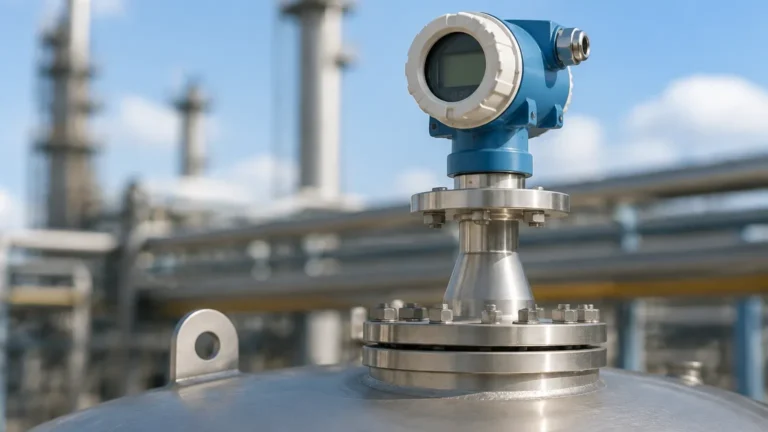
Loop Powered Radar Level Transmitter
Loop Powered Radar Level Transmitter: Engineering Principles and Selection Guide
In the landscape of industrial process automation, the transition from mechanical level measurement to electronic sensing has been driven by the need for higher reliability and lower maintenance. Among the various technologies available, the loop powered radar level transmitter has emerged as a preferred solution for liquid and solid level monitoring. By combining the precision of microwave technology with the efficiency of a two-wire current loop, these instruments provide a robust method for measuring tank levels without physical contact with the media.
Selecting the appropriate Radar Level Meters requires a technical understanding of microwave physics, vessel geometry, and the electrical constraints of loop-powered circuitry. This guide examines the operating principles, selection criteria, and installation requirements essential for engineering professionals and procurement specialists.
Measurement Principles of Radar Technology
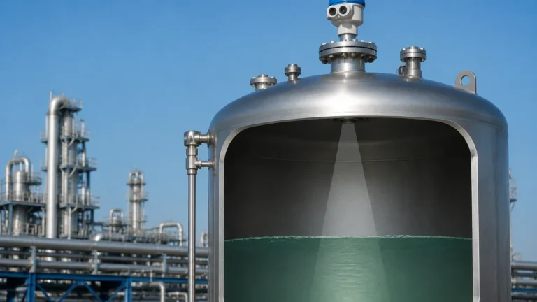
Radar level measurement operates on the principle of "Time of Flight" (ToF) using electromagnetic waves. Unlike ultrasonic sensors, which use sound waves and are affected by air temperature and pressure, radar signals travel at the speed of light and are virtually unaffected by the atmosphere within the vessel.
Pulse Radar vs. FMCW
There are two primary methods used by a loop powered radar level transmitter to determine distance:
1. Pulse Radar: The transmitter emits a short microwave pulse toward the product surface. The signal reflects off the surface and returns to the antenna. The instrument measures the time elapsed between emission and reception. While energy-efficient and suitable for 2-wire configurations, pulse radar may struggle with low-dielectric materials or heavy surface turbulence.
2. FMCW (Frequency Modulated Continuous Wave): The transmitter emits a continuous signal with a constantly changing frequency. The difference in frequency between the emitted signal and the reflected signal is proportional to the distance. FMCW offers significantly higher accuracy and a better signal-to-noise ratio, making it the standard for high-precision industrial applications, even within the power constraints of a 4-20 mA loop.
The Role of Dielectric Constant (εr)
The ability of a radar signal to reflect off a medium depends on the material's dielectric constant ($ε_r$). Water has a high dielectric constant (~80), providing a very strong reflection. In contrast, hydrocarbons like oil or solvents have low dielectric constants (1.7 to 2.5), which reflect only a small portion of the microwave energy. Modern radar level meters utilize advanced signal processing to detect these weak echoes, but the $ε_r$ value remains a critical factor in determining the maximum measurable range.
Advantages of Loop-Powered (2-Wire) Systems
A loop powered radar level transmitter is designed to operate on a standard 4-20 mA DC current loop. This configuration provides several advantages in an industrial B2B context:
* Reduced Wiring Costs: Because the same pair of wires carries both the power supply (typically 24V DC) and the measurement signal, cabling requirements are halved compared to 4-wire systems.
* Simplified Integration: 2-wire transmitters are compatible with existing PLC and DCS analog input cards without requiring additional power distribution blocks at the field level.
* Intrinsic Safety: Many loop-powered devices are designed for use in hazardous areas (ATEX/IECEx). The low power consumption makes it easier to implement intrinsically safe (IS) barriers, preventing electrical sparks in explosive atmospheres.
Technical Selection Criteria
When specifying a radar level meter, engineers must match the instrument's frequency and antenna design to the specific process environment.
Frequency Options
| Frequency | Common Applications | Advantages | Limitations |
| :— | :— | :— | :— |
| 6 GHz (C-Band) | Large tanks with heavy foam or steam. | Penetrates vapor and foam better than high frequencies. | Large antenna required; wide beam angle (~20°-30°). |
| 26 GHz (K-Band) | Standard process tanks, chemicals, oils. | Balanced performance; manageable antenna size. | Sensitive to heavy condensation or buildup on the antenna. |
| 80 GHz (W-Band) | Small vessels, narrow nozzles, solids. | Extremely narrow beam angle (as low as 3°); high precision. | Higher cost; signal can be blocked by very thick dust or foam. |
| Guided Wave (GWR) | Low dielectric liquids, bypass chambers. | Signal follows a probe; unaffected by foam or internal obstructions. | Contact-based; susceptible to probe coating or mechanical stress. |
Antenna Types
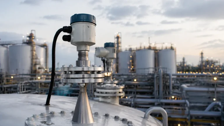
* Horn Antennas: The most common type for non-contact radar. Available in various diameters; larger horns produce narrower beams.
* Parabolic Antennas: Used for long-range measurements (up to 70-100 meters) or for measuring solids where the surface may be angled.
* Lens/Encapsulated Antennas: Often made of PTFE or PP, these are flush-mounted and ideal for corrosive chemical environments or hygienic food-grade applications.
Installation Considerations and Constraints
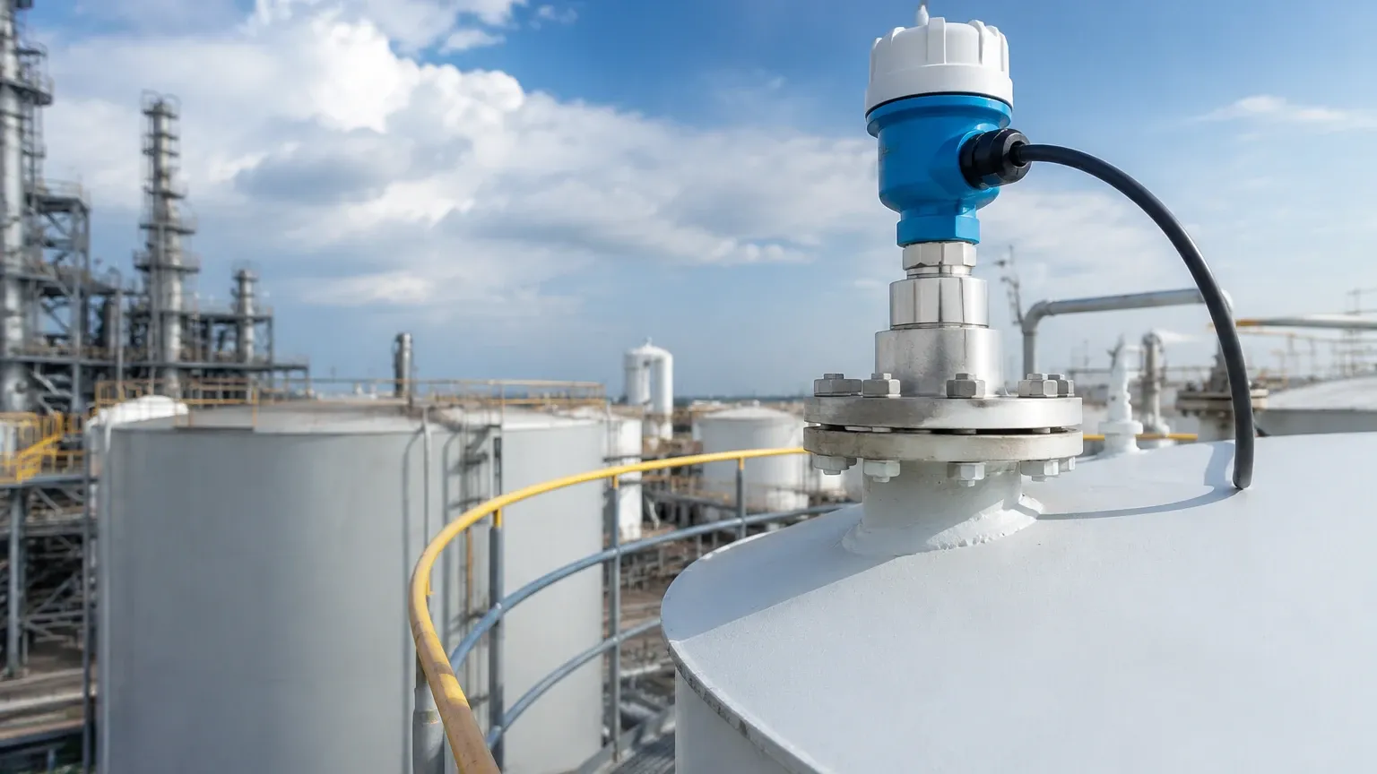
Correct installation is the most critical factor in ensuring the long-term accuracy of a radar level meter. Even the most advanced loop powered radar level transmitter will fail if it is poorly positioned.
1. Blocking Distance (Dead Zone)
Every radar transmitter has a "blocking distance" near the antenna where measurement is not possible. This is typically between 50mm and 300mm depending on the frequency. Engineers must ensure the maximum fill level of the tank does not enter this zone.
2. Nozzle Geometry
The nozzle on which the radar is mounted should be as short as possible. If the nozzle is too long or narrow, the radar signal may reflect off the nozzle walls, creating "false echoes" that interfere with the actual level reading. For high-frequency 80GHz radars, nozzle interference is significantly reduced due to the narrow beam.
3. Internal Obstructions
Radar signals spread out in a cone. Any internal structures within this cone—such as agitators, heating coils, ladders, or support beams—will create reflections. While modern software can "map out" these static obstructions, it is best practice to install the sensor in a location with a clear line of sight to the product surface.
4. Mounting Position
* Distance from Wall: The sensor should typically be mounted at 1/4 to 1/3 of the tank diameter away from the wall to avoid interference from wall reflections.
* Avoid the Center: In vertical cylindrical tanks with domed tops, mounting the sensor in the exact center can cause multiple reflections to converge, leading to signal errors.
* Inlet Streams: Never mount the sensor directly above the tank inlet, as the falling product will interfere with the radar signal.
Application Risks and Limitations
While highly versatile, radar technology is not a universal solution. Certain conditions present risks to measurement stability:
* Heavy Foam: While some foam allows radar signals to pass through, dense, thick foam (like shaving cream) can absorb the microwave signal entirely, resulting in a "loss of echo" error.
* Vacuum and Pressure: While radar works in a vacuum, extreme pressures can change the dielectric properties of the gas phase above the liquid, requiring compensation factors in the transmitter settings.
* Antenna Buildup: In applications involving crystallizing liquids or heavy dust, material may accumulate on the antenna. While some radar units feature "self-cleaning" algorithms or air purge connections, heavy buildup will eventually attenuate the signal.
Buyer’s Checklist for International Procurement
When sourcing a loop powered radar level transmitter for industrial projects, international buyers should confirm the following technical specifications with the manufacturer:
1. Process Connection: Ensure the flange or thread standard (ANSI, DIN, JIS) matches the vessel specifications.
2. Wetted Materials: Confirm that the antenna and seal materials (e.g., SS316L, PTFE, Viton, Kalrez) are chemically compatible with the process media.
3. Communication Protocol: Beyond the 4-20 mA signal, determine if HART, Modbus RTU, or Profibus PA is required for remote configuration and diagnostics.
4. Certification: Verify required safety certifications such as CE, SIL2 (for safety-instrumented systems), and explosion-proof ratings (Ex d or Ex i).
5. Environmental Limits: Check the operating temperature range for the electronics housing, especially for outdoor installations in extreme climates.
Frequently Asked Questions (FAQ)
Q: Can a loop powered radar level transmitter measure solids like grain or cement?
A: Yes. However, solids often have low dielectric constants and create angled surfaces that scatter the signal. High-frequency (80GHz) radars with high sensitivity are generally recommended for solids to ensure a reliable return echo.
Q: How does a 2-wire radar compare to an ultrasonic level sensor?
A: Radar is superior in most industrial process conditions. Ultrasonic sensors are limited by air temperature fluctuations, heavy dust, and vacuum conditions, whereas radar remains accurate across these variables. Radar is typically more expensive but offers lower total cost of ownership through reduced maintenance.
Q: What is the maximum distance a loop-powered radar can measure?
A: Most modern units can measure up to 30 meters (approx. 100 feet) in a 2-wire configuration. Specialized long-range models can reach up to 100 meters, though signal strength at these distances depends heavily on the dielectric constant of the target material.
Q: Is calibration required on-site?
A: Usually not. Radar transmitters are factory-calibrated based on distance. On-site setup typically involves "parameterization"—entering the tank height, the 4mA point (empty), and the 20mA point (full) via a local display or HART communicator.
Conclusion
The implementation of a loop powered radar level transmitter represents a significant upgrade for industrial level monitoring, providing non-contact precision within a cost-effective 2-wire electrical architecture. By understanding the relationship between frequency, dielectric constants, and vessel geometry, engineering teams can select a solution that minimizes downtime and maximizes process safety. For complex applications involving agitated surfaces or corrosive chemicals, consulting with a specialized manufacturer like Welk ensures that the selected Radar Level Meters are optimized for the specific challenges of the industrial environment.