Magnetrol Radar Level Transmitter Manual
Magnetrol Radar Level Transmitter Manual: An Engineering Guide to Selection and Installation
In the landscape of industrial automation, the precision of level measurement is a cornerstone of process safety and efficiency. For engineers and procurement specialists, the magnetrol radar level transmitter manual serves as the primary technical authority for deploying high-performance instrumentation in challenging environments. Whether managing volatile chemicals, high-pressure steam, or viscous hydrocarbons, understanding the underlying principles and installation constraints detailed in these technical documents is essential for long-term operational success.
This guide provides a comprehensive overview of radar level measurement technology, drawing on the engineering standards typically found in technical manuals for high-end instruments like those produced by Welk and other industry leaders. By focusing on both Guided Wave Radar (GWR) and non-contact microwave technology, we aim to clarify the selection process for Radar Level Meters.
1. Understanding Measurement Principles
Before consulting a specific magnetrol radar level transmitter manual for wiring or configuration, it is vital to understand the two primary methods of radar level measurement used in modern industrial transmitters.
Guided Wave Radar (GWR)
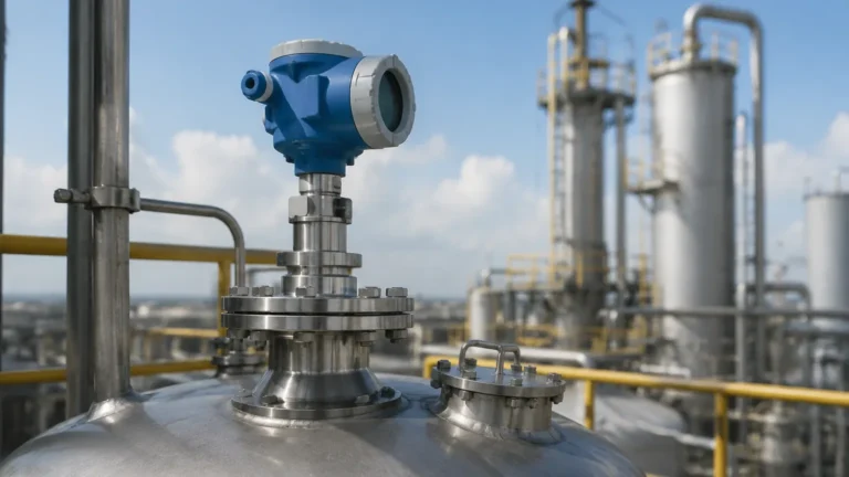
Guided Wave Radar is based on the principle of Time Domain Reflectometry (TDR). The transmitter generates low-energy electromagnetic pulses that are guided along a physical probe (waveguide). When these pulses reach the surface of the process media, the change in the dielectric constant causes a portion of the pulse to reflect back to the transmitter.
The device measures the time-of-flight to calculate the distance. Because the signal is contained within a probe, GWR is exceptionally resilient against surface foam, turbulence, and changes in vapor space composition. It is the preferred choice for interface measurement (e.g., oil over water).
Non-Contact Radar
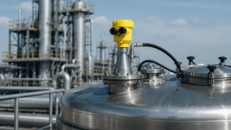
Non-contact radar level meters emit microwave signals through the air. These signals reflect off the liquid or solid surface and return to the antenna. Modern transmitters often use Frequency Modulated Continuous Wave (FMCW) or Pulse Burst technology. This method is ideal for corrosive media or applications where the instrument cannot come into contact with the process fluid. However, it requires a clear line of sight and can be influenced by internal tank obstructions or heavy foam.
2. Technical Selection Criteria
Selecting the correct instrument requires a deep dive into the technical specifications found in the magnetrol radar level transmitter manual. The following table summarizes the key considerations for choosing between GWR and non-contact technologies.
| Feature | Guided Wave Radar (GWR) | Non-Contact Radar |
| :— | :— | :— |
| Media Type | Liquids, Slurries, Interface | Liquids, Solids, Granules |
| Dielectric Constant (εr) | Low (≥ 1.4) | Moderate to High (≥ 1.9) |
| Surface Conditions | Effective with foam/turbulence | Affected by heavy foam/agitation |
| Internal Obstructions | Not affected (if probe is clear) | Requires clear signal path |
| Max Range | Up to 45m (150 ft) | Up to 100m (328 ft) |
| Mounting | Top-mounted (Probe required) | Top-mounted (No contact) |
Critical Process Parameters
When reviewing a manual, engineers must verify the following limits:
- Process Temperature: Standard units often handle up to 200°C (392°F), while specialized high-temperature versions can exceed 450°C (842°F).
- Process Pressure: High-pressure seals are required for applications exceeding 40 bar (580 psi), with some models rated up to 430 bar (6250 psi).
- Dielectric Constant (εr): The reflectivity of the media. Low dielectric fluids (like liquid CO2 or hydrocarbons) require more sensitive electronics or coaxial probes.
3. Installation Considerations and Constraints
A significant portion of any magnetrol radar level transmitter manual is dedicated to mechanical installation. Incorrect mounting is the leading cause of signal loss and measurement inaccuracy.
Nozzle Geometry
The nozzle height and diameter significantly impact the signal. For non-contact radar, the antenna should ideally extend below the nozzle to prevent "ringing" or internal reflections. If the nozzle is long and narrow, the manual will specify a minimum clearance to avoid interference with the nozzle wall.
The "Dead Zone" or Blocking Distance
Every radar transmitter has a dead zone (upper and lower) where measurement is not possible or accurate.
- Upper Dead Zone: The area near the flange or antenna where the signal is too close to be processed. This is typically between 50mm and 300mm (2" to 12").
- Lower Dead Zone: Near the end of a GWR probe or the bottom of the tank, where the signal may transition into the tank floor reflection.
Probe Selection for GWR
1. Coaxial Probes: Best for low dielectric liquids and turbulent surfaces. They provide the highest signal-to-noise ratio.
2. Twin Rod Probes: Used for long-range applications in cleaner liquids.
3. Single Rod Probes: Ideal for viscous media or applications prone to coating and buildup, as they are the easiest to clean.
4. Application Risks and Limitations
While Radar Level Meters are highly versatile, they are not universal solutions. The magnetrol radar level transmitter manual will typically list "Application Limitations" which include:
- Heavy Coating: While GWR can handle some buildup, conductive coating (like metallic slurries) can bridge the probe to the tank wall, causing a false high-level reading.
- Vapor and Condensation: High-pressure steam can change the propagation speed of the radar pulse. Advanced transmitters include "Vapor Compensation" features that use a reference target to calibrate the signal in real-time.
- Foam: While GWR is generally immune to foam, non-contact radar may see the top of the foam as the liquid level, or the foam may absorb the signal entirely, resulting in a "Loss of Echo" (LOE) error.
5. Configuration and Calibration
Modern industrial level transmitters are typically configured via HART, Foundation Fieldbus, or Profibus. The manual provides a step-by-step guide to the "Quick Start" menu, which usually requires four basic inputs:
1. Units of Measurement: (m, cm, mm, ft, in).
2. Probe/Antenna Length: The physical length of the sensing element.
3. Dielectric Constant: An estimate of the media's εr.
4. 0% and 100% Levels: Mapping the 4-20mA output to specific physical distances.
False Echo Mapping
One of the most powerful features found in a magnetrol radar level transmitter manual is the instruction for "Echo Mapping" or "Blanking." This allows the transmitter to record all static reflections (from ladders, agitators, or baffles) while the tank is empty and ignore them during actual operation. This ensures that the instrument only tracks the actual liquid surface.

6. Maintenance and Troubleshooting
Industrial environments are harsh, and even the most robust radar meters require occasional checks. The troubleshooting section of the manual is an invaluable resource for plant technicians.
Common Error Codes
- Low Signal Strength: Often caused by heavy buildup on the antenna or probe. Cleaning the sensing element usually resolves this.
- Invalid Configuration: Occurs when the programmed probe length does not match the physical reflections detected.
- Electronic Failure: Indicated by a fixed 3.6mA or 22mA output (depending on NAMUR NE43 safety settings).
7. International Buyer's Checklist
For procurement professionals sourcing equipment for global projects, the magnetrol radar level transmitter manual provides the necessary documentation for compliance and compatibility. Before finalizing a purchase, confirm the following:
1. Hazardous Area Certifications: Ensure the manual specifies ATEX, IECEx, or FM ratings suitable for the installation zone (e.g., Zone 0, 1, or 2).
2. SIL Rating: For Safety Instrumented Systems, verify the Safety Integrity Level (typically SIL 2 or SIL 3) and the required SFF (Safe Failure Fraction).
3. Material Traceability: Check for MTRs (Material Test Reports) for wetted parts, especially for 316/316L Stainless Steel, Hastelloy, or Monel.
4. Ingress Protection: Verify the housing rating (IP66, IP67, or IP68) to ensure the electronics are protected from moisture and dust.
Conclusion
The magnetrol radar level transmitter manual is an essential roadmap for the lifecycle of a level measurement instrument. From the initial measurement principle selection to the nuances of false echo mapping, these documents provide the technical boundaries required to maintain process integrity. By adhering to the installation guidelines and understanding the limitations of the technology, engineers can ensure that their Radar Level Meters provide accurate, repeatable data for years to come.
For those seeking customized solutions, manufacturers like Welk offer a range of radar technologies tailored to specific industrial needs, backed by the technical support and documentation necessary for seamless integration into modern control systems.
***
Frequently Asked Questions (FAQ)
Q: Can a radar level transmitter measure the interface between two liquids?
A: Yes, Guided Wave Radar (GWR) is particularly effective at interface measurement, such as oil over water. The manual will specify that the upper liquid must have a lower dielectric constant than the lower liquid for accurate detection.
Q: What happens if the dielectric constant of my media changes?
A: In GWR, a change in dielectric constant primarily affects the signal amplitude but not the time-of-flight, so the level reading remains accurate. In non-contact radar, extreme changes in vapor space dielectric (due to high pressure) may require vapor compensation.
Q: How often should a radar level meter be calibrated?
A: Radar meters are solid-state devices with no moving parts, meaning they do not "drift" like mechanical gauges. However, annual verification is recommended to ensure no significant buildup or corrosion has occurred on the probe or antenna.
Q: Is radar technology suitable for solids like grain or plastic pellets?
A: Yes, but non-contact radar is generally preferred for solids. The manual will suggest using a gimbal flange to aim the radar at the "angle of repose" of the solid material to maximize signal return.