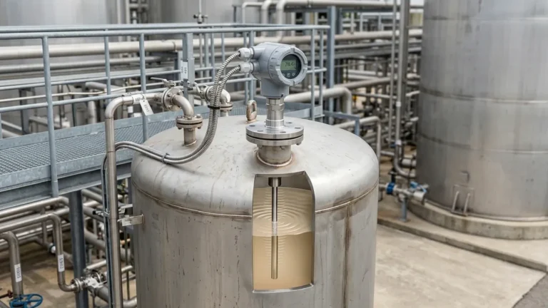
Non Contact Radar Level Transmitter Working Principle
Non Contact Radar Level Transmitter Working Principle: A Technical Engineering Guide
In the landscape of industrial automation, precise level measurement is a cornerstone of process safety, inventory management, and operational efficiency. Among the various technologies available, non-contact radar level transmitters have emerged as a preferred solution for challenging environments. Unlike contact-based methods, these instruments operate without physical interaction with the process medium, significantly reducing maintenance requirements and the risk of sensor degradation.
Understanding the non contact radar level transmitter working principle is essential for engineers and procurement specialists to ensure the selected instrumentation aligns with the specific dielectric properties, vessel geometries, and atmospheric conditions of their application. This guide provides a technical overview of how Radar Level Meters function, their frequency variations, and the critical factors influencing their performance.
1. Core Measurement Principles
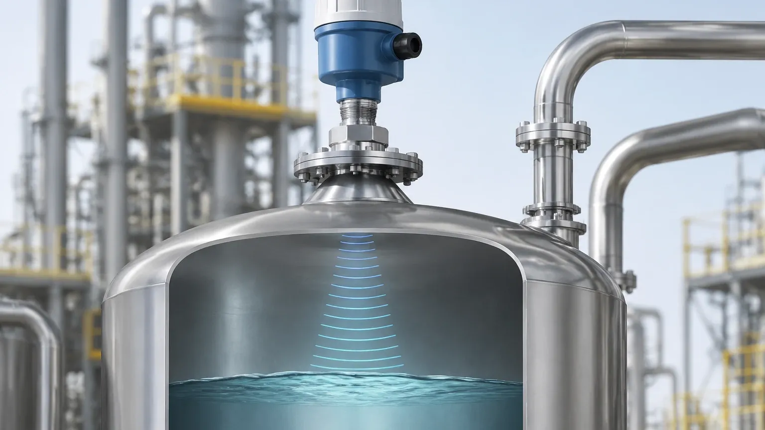
Non-contact radar level transmitters utilize electromagnetic waves in the microwave frequency range to detect the distance to a product surface. The fundamental principle relies on the "Time of Flight" (ToF) concept: measuring the time it takes for a microwave signal to travel from the sensor to the material surface and back again. Since the speed of light (and thus microwaves) is constant in a vacuum and relatively stable in air, the distance can be calculated using the formula:
Distance = (Speed of Light × Travel Time) / 2
In industrial practice, there are two primary methods used to process these signals: Pulse Radar and Frequency Modulated Continuous Wave (FMCW).
Pulse Radar (Time of Flight)
Pulse radar instruments emit a short microwave pulse toward the medium. The sensor then switches to a receiving mode to wait for the reflected echo. The time elapsed between emission and reception is measured directly. While effective for many standard applications, pulse radar often requires sophisticated signal processing to distinguish the true level from background noise and internal tank obstructions.
Frequency Modulated Continuous Wave (FMCW)
FMCW is the more advanced and increasingly common non contact radar level transmitter working principle. Instead of short pulses, the transmitter emits a continuous signal with a frequency that changes linearly over time (a frequency ramp).
When the reflected signal returns to the sensor, it is compared with the signal currently being emitted. Because the emitted frequency has shifted during the signal's travel time, a frequency difference (or "beat frequency") is created. This frequency difference is directly proportional to the distance. FMCW technology typically offers higher accuracy and a better signal-to-noise ratio than pulse-based systems, making it ideal for high-precision requirements.
2. The Influence of Frequency: 6GHz to 80GHz
The frequency at which a radar level meter operates dictates its beam angle, sensitivity, and ability to penetrate atmospheric interference like steam or dust.
* C-Band (approx. 6 GHz): These low-frequency transmitters are characterized by a wide beam angle. They are highly resilient to heavy foam, steam, and condensation on the antenna. However, because the beam is wide, they require large installation nozzles and are prone to interference from internal tank structures like agitators or ladders.
* K-Band (approx. 26 GHz): This is the industrial standard for many years. It offers a balance between a narrower beam angle and a relatively small antenna size. It is suitable for a wide range of liquids and solids where moderate dust or vapor is present.
* W-Band (approx. 80 GHz): The current state-of-the-art in radar technology. High-frequency 80GHz radar produces a very narrow beam (often as small as 3°). This allows the signal to avoid internal obstructions and permits installation in small nozzles or through ball valves. It also provides superior resolution, making it the best choice for measuring low-dielectric materials or levels in tall, narrow silos.
3. The Role of the Dielectric Constant ($ε_r$)
The effectiveness of a radar reflection is primarily determined by the dielectric constant ($ε_r$) of the medium being measured. The dielectric constant is a measure of a material's ability to reflect electromagnetic energy.
* High Dielectric Materials ($ε_r > 10$): Water-based liquids (water has an $ε_r$ of approx. 80) provide very strong reflections, making them easy to measure even with significant surface turbulence.
* Low Dielectric Materials ($ε_r < 2$): Hydrocarbons, oils, and some solids have low dielectric constants. In these cases, a large portion of the radar signal may pass through the material rather than reflecting. For these applications, high-sensitivity FMCW radar or guided wave radar may be necessary.
4. Selection Criteria and Comparison
Choosing the right radar level meter involves balancing the physical properties of the medium with the mechanical constraints of the vessel.
| Feature | 6 GHz Radar | 26 GHz Radar | 80 GHz Radar |
| :— | :— | :— | :— |
| Beam Angle | Wide (approx. 20°-30°) | Medium (approx. 8°-12°) | Narrow (approx. 3°-4°) |
| Nozzle Size | Large (≥ DN150 / 6") | Medium (DN50 – DN100) | Small (≥ DN20 / ¾") |
| Steam/Foam Resistance | Excellent | Good | Moderate |
| Accuracy | ± 5-10 mm | ± 2-3 mm | ± 1 mm |
| Best Application | Heavy steam, boiling liquids | Standard chemical storage | Tall silos, narrow tanks, high precision |
5. Installation Considerations and Best Practices
Even the most advanced radar transmitter will fail if installed incorrectly. To ensure the non contact radar level transmitter working principle remains effective, engineers should adhere to the following installation guidelines:
Nozzle Positioning
The transmitter should not be installed in the center of a tank with a domed roof, as the geometry can focus multiple reflections back to the sensor, causing signal interference. Conversely, it must be placed far enough from the tank wall (typically 1/6th of the tank diameter) to avoid wall reflections.
Obstruction Avoidance
The radar beam is cone-shaped. Any internal structures—such as heating coils, agitators, or ladders—that enter this cone will create "false echoes." While modern software can "map out" these echoes, it is best practice to position the sensor where the beam has a clear path to the product surface.
Nozzle Height and Diameter
The nozzle should be as short and wide as possible. If a nozzle is too long or narrow, the radar signal may reflect off the internal weld or the bottom edge of the nozzle before it even enters the tank, creating a large "blind zone" or dead band at the top of the measurement range.
Orientation
For liquid applications, the sensor must be mounted perfectly vertical. For solid applications (like grain or powders) where the material forms a cone, an aiming flange (swivel holder) is often required to angle the sensor perpendicular to the slope of the material for maximum signal return.
6. Limitations and Application Risks
While highly versatile, non-contact radar is not a universal solution. Engineers must be aware of the following limitations:
1. Heavy Foam: While C-band radar can penetrate some foam, extremely dense, thick foam (like shaving cream) can absorb the microwave signal entirely, leading to a loss of echo.
2. Vacuum Conditions: While radar works in a vacuum, the electronics and housing must be rated for the specific pressure and temperature extremes of the process.
3. Extremely Low Dielectric Media: If the $ε_r$ is below 1.4, the reflection may be too weak for standard non-contact radar. In these instances, a stilling well or guided wave radar (contacting) is often recommended.
4. Multiple Interfaces: Non-contact radar typically only tracks the top surface. If you need to measure the interface between oil and water, guided wave radar is usually the superior choice.
7. Frequently Asked Questions (FAQ)
Q: Does dust affect non-contact radar?
A: Generally, no. Microwaves penetrate dust easily. However, in extremely high-dust environments (like pneumatic filling of a cement silo), very high-frequency radar (80GHz) is preferred because its narrow beam reduces reflections from the dust cloud itself.
Q: Can radar measure through a plastic tank roof?
A: Yes. Because plastic has a low dielectric constant, microwaves can pass through it. This allows for "non-invasive" measurement where the sensor is mounted outside a plastic IBC or storage tank.
Q: What is the "Dead Zone"?
A: The dead zone (or blocking distance) is the area immediately below the sensor where measurement is not possible. This is typically between 50mm and 300mm (2" to 12"), depending on the frequency and antenna design.
Q: Is calibration required?
A: Non-contact radar transmitters are typically pre-calibrated from the factory. On-site configuration usually only involves entering the tank height, the 4-20mA range points, and performing a "false echo suppression" scan to map out internal obstructions.
Conclusion
The non contact radar level transmitter working principle offers a robust, low-maintenance solution for modern industrial level sensing. By understanding the nuances of FMCW technology, frequency selection, and the impact of dielectric constants, process engineers can specify instrumentation that provides reliable data for years. Whether managing corrosive chemicals, high-temperature bitumen, or simple water storage, selecting the correct radar configuration is the first step toward a stable and automated process environment.
Download Non Contact Radar Level Transmitter Working Principle as a PDF