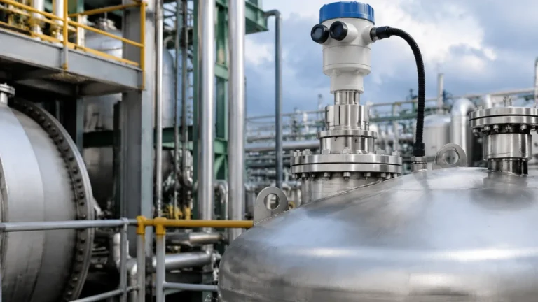
Non Contact Radar Level Transmitter
In the landscape of industrial automation, the non contact radar level transmitter has emerged as a cornerstone technology for precise, reliable, and maintenance-free liquid and solid level measurement. Unlike traditional contact-based methods, such as float switches or guided wave radar, non-contact radar instruments operate without physical interaction with the process media. This characteristic makes them indispensable for applications involving corrosive chemicals, hygienic food processing, or abrasive bulk solids.
Selecting the appropriate Radar Level Meters requires a deep understanding of the underlying physics, the specific process environment, and the mechanical constraints of the vessel. This guide provides a technical overview of non-contact radar technology to assist engineers and procurement specialists in making informed decisions.
Measurement Principles: Pulse vs. FMCW
Non-contact radar transmitters generally utilize two primary methods for calculating distance: Pulse Radar and Frequency Modulated Continuous Wave (FMCW).
Pulse Radar (Time of Flight)
Pulse radar instruments emit a short microwave signal toward the product surface. The signal travels at the speed of light, reflects off the media, and returns to the sensor antenna. The transmitter measures the total transit time (Time of Flight). Since the speed of light is constant, the distance is calculated as:
Distance = (Speed of Light × Transit Time) / 2
While effective for many standard liquid applications, pulse radar can struggle with low-dielectric media or environments with significant surface turbulence due to a lower signal-to-noise ratio compared to modern alternatives.
FMCW (Frequency Modulated Continuous Wave)
FMCW technology is the current standard for high-performance industrial applications. Instead of a pulse, the transmitter emits a continuous signal with a constantly changing frequency (a frequency sweep). When the reflected signal is received, it is compared to the signal being emitted at that exact moment. The difference in frequency (the "beat frequency") is directly proportional to the distance to the product surface.
FMCW provides superior signal processing capabilities, allowing the instrument to filter out noise from agitators, internal tank structures, and foam more effectively than pulse-based systems.
Key Technical Selection Criteria
Choosing a non contact radar level transmitter involves more than selecting a range. Several variables dictate the reliability of the measurement.
1. Operating Frequency (26GHz vs. 80GHz)
The frequency of the radar signal determines the beam angle and the instrument's ability to handle difficult process conditions.
* 26GHz Radar: Often referred to as the "workhorse" of the industry. It features a wider beam angle, which can be advantageous in applications where heavy foam is present, as the wider signal can sometimes find a path through the foam to the liquid surface. However, the wider beam requires more clear space inside the tank to avoid false reflections from walls or pipes.
* 80GHz Radar: Represents the latest advancement in radar technology. The higher frequency allows for a much narrower beam angle (often as low as 3°). This precision makes it ideal for tall, narrow tanks, vessels with internal obstructions, or media with low dielectric constants. It also allows for smaller antenna sizes, which simplifies installation on small nozzles.
2. Dielectric Constant (εr)
The dielectric constant of the media is the most critical factor in signal reflection. Materials with high dielectric constants (e.g., water, εr ≈ 80) reflect signals strongly. Hydrocarbons, oils, and some solids have low dielectric constants (εr < 2), meaning they absorb or transmit much of the radar energy, leaving a very weak reflection for the sensor to detect. When selecting a transmitter, ensure the device sensitivity matches the εr of the target media.
3. Process Temperature and Pressure
Radar electronics are sensitive to heat. While the antenna (the part inside the tank) can often withstand temperatures exceeding 200°C (392°F) and high pressures, the transmitter housing must be protected. Engineers should consider cooling fins or remote-mounted electronics for extreme thermal environments.
Technical Comparison: 26GHz vs. 80GHz Radar Level Meters
| Feature | 26GHz Radar | 80GHz Radar |
| :— | :— | :— |
| Beam Angle | 8° to 20° (Typical) | 3° to 8° (Typical) |
| Accuracy | ±3 mm to ±5 mm | ±1 mm |
| Max Range | Up to 30 meters | Up to 120 meters |
| Nozzle Size | Requires larger nozzles (DN50+) | Can use very small nozzles (DN20+) |
| Dust/Vapor Resistance | High | Excellent |
| Internal Obstructions | Sensitive to interference | Easily avoids obstructions |
Installation Guidelines and Engineering Constraints
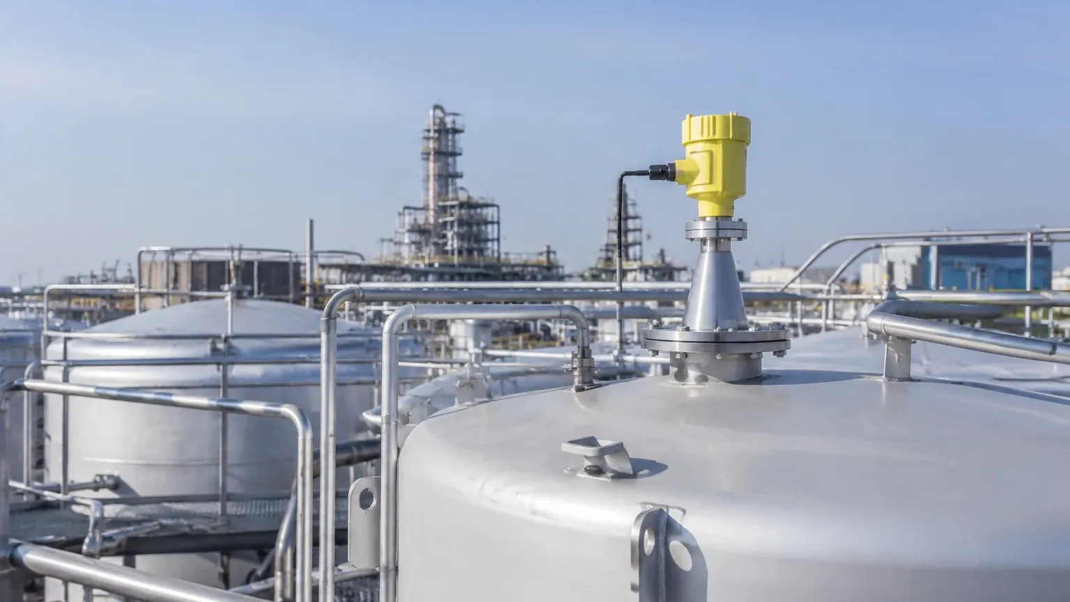
Correct installation is paramount to the performance of a non contact radar level transmitter. Even the most advanced sensor will fail if placed incorrectly.
Nozzle Dynamics
The nozzle on which the radar is mounted should be as short as possible. If the nozzle is too long or narrow, the radar signal may reflect off the internal edges of the nozzle before it even enters the tank, creating a "ringing" effect that masks the true level signal. For 80GHz units, this is less of a concern, but for 26GHz units, the antenna should ideally extend slightly below the bottom of the nozzle.
Distance from Tank Walls
To avoid "wall cling" and interference from the vessel sides, the transmitter should typically be installed at a distance of 1/6th to 1/4th of the tank diameter from the wall. It should never be mounted in the exact center of a tank with a domed roof, as this can cause multiple reflections to converge at the sensor, leading to signal errors.
Avoiding Obstructions
Internal structures such as ladders, heating coils, and agitator blades create "false echoes." While modern software can perform a "False Echo Suppression" (mapping out these static reflections), it is best practice to install the sensor in a location where the signal beam has a clear, unobstructed path to the media surface.
The "Dead Zone"
Every radar transmitter has a blocking distance (dead zone) near the antenna where measurement is not possible. This is typically between 50mm and 300mm depending on the model. Ensure the maximum expected liquid level does not enter this zone.
Application Risks and Signal Interference
While highly versatile, non-contact radar is not a universal solution for every problem. Certain conditions require specific engineering adjustments:
1. Heavy Foam: Thick, dense foam can absorb the radar signal entirely. In such cases, 26GHz radar or even a contact-based guided wave radar may be more effective than high-frequency 80GHz units.
2. Heavy Turbulence: Rapidly moving liquid surfaces can scatter the radar signal. This is often mitigated by using a stilling well—a vertical pipe that stabilizes the liquid surface for the radar to measure.
3. Condensation and Buildup: If the media is prone to off-gassing or splashing, material may build up on the antenna lens. While many Radar Level Meters feature PTFE or PEEK lenses that resist buildup, significant accumulation will eventually attenuate the signal. Air purging systems are often used to keep the antenna face clean in dusty or high-moisture environments.
Buyer’s Checklist for International Procurement
When sourcing a non contact radar level transmitter for industrial projects, ensure the following specifications are confirmed with the manufacturer:
* Media Properties: What is the dielectric constant (εr)? Is the media corrosive or abrasive?
* Vessel Geometry: What is the total height, diameter, and nozzle size? Are there internal obstructions?
* Process Conditions: What are the maximum and minimum operating temperatures and pressures?
* Output Requirements: Is a standard 4-20mA HART signal sufficient, or is a digital protocol like RS485 Modbus, Profibus, or Foundation Fieldbus required?
* Certifications: Does the environment require Explosion-Proof (Ex d) or Intrinsically Safe (Ex i) ratings? For food and pharma, are 3A or EHEDG certifications necessary?
Frequently Asked Questions (FAQs)
Q: Can non-contact radar measure through a plastic tank wall?
A: Yes. If the tank is made of a non-conductive material like PE, PP, or PVC and is not reinforced with metal, the radar signal can pass through the top of the tank, allowing for measurement without any openings in the vessel. This is common in chemical IBCs and storage tanks.
Q: How does dust affect the measurement in solid silos?
A: High-frequency 80GHz radar is exceptionally good at penetrating heavy dust during filling cycles. Unlike ultrasonic sensors, which are affected by air density and sound absorption, radar signals are largely unaffected by the atmosphere inside the tank.
Q: Is a stilling well always necessary for agitated liquids?
A: No. With modern FMCW signal processing and high-frequency beams, many radar units can track a turbulent surface directly. A stilling well is only recommended if the turbulence is extreme or if there is heavy, persistent foam that the radar cannot penetrate.
Q: What is the lifespan of a non-contact radar transmitter?
A: Because there are no moving parts and no contact with the media, these instruments often last 10 to 15 years in standard industrial environments, provided the electronics are protected from extreme heat and moisture ingress.
By following these engineering principles and selection criteria, process facilities can ensure high-accuracy level monitoring, reducing the risk of overflows, dry-runs, and unnecessary maintenance downtime. For specific application engineering support, it is recommended to consult with technical specialists who can provide customized mounting and configuration advice based on the unique characteristics of your facility.