Omega Radar Level Transmitter
Omega Radar Level Transmitter: An Engineering Guide to Selection and Application
In the landscape of industrial process control, the accurate measurement of liquid and solid levels is fundamental to operational safety, inventory management, and process efficiency. Among the various technologies available, Radar Level Meters have emerged as the preferred solution for challenging environments. Specifically, the omega radar level transmitter represents a class of high-frequency, non-contact instruments designed to overcome the limitations of traditional ultrasonic or hydrostatic sensors.
This guide provides a technical overview of radar measurement principles, selection criteria, and installation requirements essential for engineering professionals and international procurement teams.
1. Measurement Principles: How Radar Works
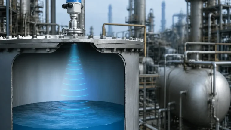
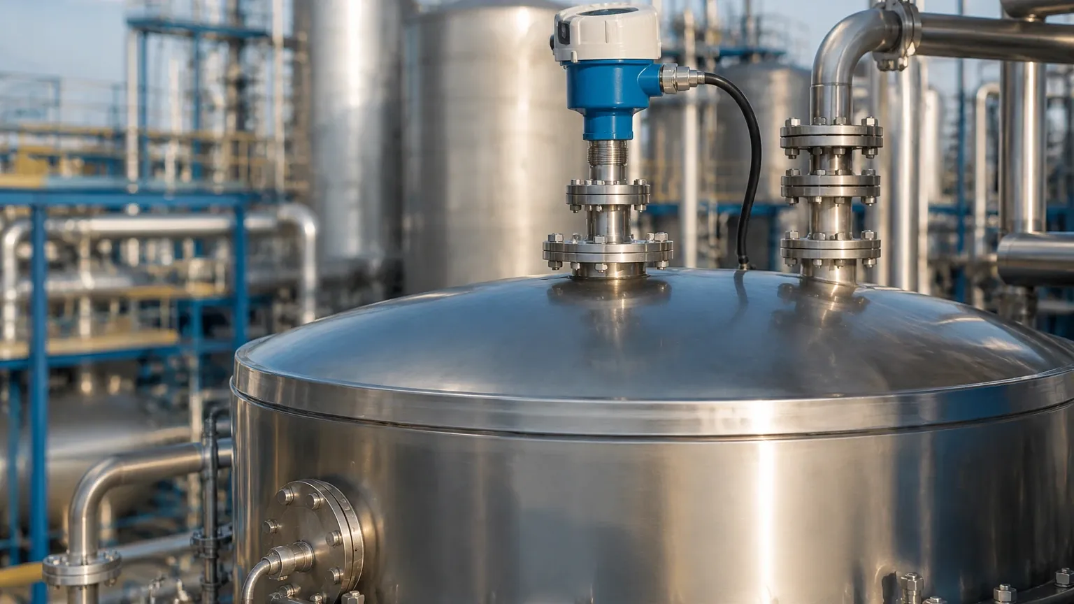
Radar level measurement is based on the Time of Flight (ToF) principle. The transmitter, mounted at the top of a vessel, emits electromagnetic pulses or continuous waves toward the product surface. These waves travel at the speed of light, reflect off the material surface, and return to the sensor's antenna.
Pulse Radar vs. FMCW
There are two primary methods used in modern radar transmitters:
1. Pulse Radar: The instrument sends a microwave pulse and measures the time it takes for the pulse to return. While effective, pulse radar can sometimes struggle with low-dielectric materials or turbulent surfaces due to signal-to-noise ratios.
2. FMCW (Frequency Modulated Continuous Wave): The omega radar level transmitter often utilizes FMCW technology. Instead of a single pulse, it emits a continuous signal with a constantly changing frequency. The distance is calculated by comparing the frequency difference between the emitted and received signals. FMCW provides significantly higher accuracy and better signal processing in complex environments.
The Role of Frequency
The frequency of the radar signal—typically ranging from 6 GHz to 80 GHz—determines the beam angle and the instrument's ability to penetrate dust or vapor. Higher frequencies (such as 80 GHz) allow for smaller antenna sizes and narrower beam angles, which are critical for avoiding internal tank obstructions like agitators or ladders.
2. Technical Selection Criteria
Selecting the correct radar level meter requires a detailed understanding of the process media and the vessel geometry. Engineers must evaluate several factors to ensure long-term reliability.
Dielectric Constant (εr)
The dielectric constant of the medium is the most critical factor in radar measurement. It determines how much of the electromagnetic energy is reflected back to the sensor.
* High εr (>10): Materials like water or aqueous solutions reflect signals strongly, making them easy to measure.
* Low εr (<2.0): Materials like hydrocarbons, solvents, or plastic pellets reflect very little energy. In these cases, high-sensitivity transmitters or guided wave radar may be required.
Process Conditions
* Temperature and Pressure: Standard radar sensors handle up to 150°C (302°F), but specialized high-temperature versions can reach 400°C (752°F) or higher. Pressure ratings can range from vacuum to over 40 bar (580 psi).
* Atmospheric Interference: Heavy steam, dust, or foam can attenuate the radar signal. While radar is generally superior to ultrasonic sensors in these conditions, 80 GHz technology is particularly effective at "seeing through" heavy dust in solids applications.
Selection Table for Radar Technologies
| Feature | 6 GHz / 26 GHz Radar | 80 GHz Radar (Omega Type) | Guided Wave Radar (GWR) |
| :— | :— | :— | :— |
| Application | Large tanks, simple liquids | Narrow tanks, solids, high precision | Low dielectric liquids, interface |
| Beam Angle | 10° – 20° | 3° – 8° | N/A (Contacting) |
| Accuracy | ±3 mm to ±5 mm | ±1 mm | ±2 mm |
| Max Range | Up to 30m (98 ft) | Up to 120m (393 ft) | Up to 30m (98 ft) |
| Installation | Large nozzles required | Small nozzles (1") possible | Requires probe insertion |
3. Installation Considerations and Constraints
Even the most advanced omega radar level transmitter will fail to perform if installation guidelines are ignored. Proper mounting is the key to minimizing false echoes and signal loss.
Nozzle Design
The nozzle height and diameter must be matched to the antenna type. If a nozzle is too long or too narrow, the radar signal may reflect off the nozzle walls before reaching the product. This creates a "ringing" effect that masks the true level in the upper portion of the tank (the dead zone).
Positioning and Obstructions
* Avoid the Center: Never mount a radar transmitter in the exact center of a circular tank, as this can lead to multiple reflections that interfere with the signal.
* Clear Path: Ensure the radar beam has a clear path to the surface. If an agitator or cooling coil is in the path, most modern Radar Level Meters allow for "False Echo Suppression" or "Echo Mapping," where the software learns to ignore static reflections.
* Wall Distance: Maintain a minimum distance from the tank wall (typically 200 mm to 500 mm) to prevent signal interference.
Dead Zones (Blocking Distance)
Every radar sensor has a minimum measurable distance near the antenna, known as the dead zone. If the liquid level enters this zone, the measurement becomes unreliable. Engineers must ensure the tank's maximum fill level remains below this threshold.
4. Application Risks and Limitations
While radar is highly versatile, it is not a universal solution. Certain conditions pose significant risks to measurement accuracy:
1. Heavy Foam: Dense, thick foam can absorb the radar signal entirely, preventing any reflection from reaching the sensor. If foam is a constant process element, a mechanical or guided wave solution may be more appropriate.
2. Turbulence and Vortexing: Rapidly moving surfaces can scatter the radar signal. While software filtering can mitigate this, extreme turbulence may require a bypass pipe or stilling well to provide a calm surface for measurement.
3. Condensation and Buildup: In high-humidity environments, water droplets can form on the antenna. While many omega radar level transmitters feature PTFE-coated lenses to shed moisture, heavy buildup of viscous or crystallizing media can eventually block the signal.
5. Information for International Buyers
When sourcing radar level transmitters for global projects, procurement teams should confirm the following technical details with the manufacturer to avoid compatibility issues:
* Output Protocols: Ensure the device supports the local control system (4-20mA HART, Modbus RTU, Profibus, or Foundation Fieldbus).
* Certifications: Verify hazardous area classifications (ATEX, IECEx, or UL/CSA) if the instrument is installed in explosive atmospheres.
* Process Connections: Confirm thread standards (G, NPT) or flange standards (ANSI, DIN, JIS) to ensure a leak-proof fit.
* Material Compatibility: Specify the wetted materials (SS316L, PTFE, Hastelloy) based on the corrosivity of the chemical being measured.
6. Frequently Asked Questions (FAQs)
Q: Can a radar level transmitter measure through a plastic tank wall?
A: Yes. Because radar waves can penetrate non-conductive materials, it is possible to measure the level inside a plastic or fiberglass tank without cutting a hole, provided the wall is not too thick and the material has a low dielectric constant.
Q: Does the density of the liquid affect radar measurement?
A: No. Unlike hydrostatic pressure transmitters, radar is independent of density, pressure, and vacuum. It only cares about the dielectric constant and the distance to the surface.
Q: How often does an omega radar level transmitter need calibration?
A: Radar is a solid-state technology with no moving parts. Once calibrated during commissioning, it typically does not drift. Periodic verification is recommended every 12 to 24 months, depending on the criticality of the process.
Q: What is the difference between 26 GHz and 80 GHz radar?
A: 80 GHz radar uses a shorter wavelength, allowing for a much narrower beam (3° to 4°) compared to 26 GHz (usually 8° to 10°). This makes 80 GHz ideal for tall, narrow silos or tanks with many internal obstructions.
7. Conclusion
The implementation of an omega radar level transmitter offers a robust, low-maintenance solution for modern industrial level sensing. By understanding the interaction between electromagnetic waves and the process media, and by adhering to strict installation protocols, facilities can achieve millimeter-level precision in even the most demanding applications. Whether for water treatment, chemical processing, or oil and gas storage, selecting the right Radar Level Meters is a critical step toward achieving total process automation.